What is PNG memory IC?

What is PNG memory IC

PNG memory IC refers to a memory chip encoded using the PNG (Pantone Numbering System) color standard.

The PNG color standard is a color matching system for accurately matching colors on different printing and digital display devices. This color standard is widely used in printing, advertising, design and other fields.

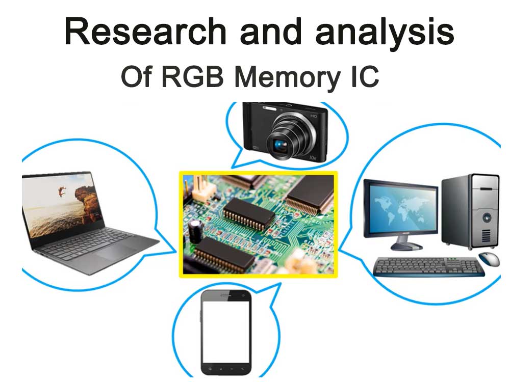
In the field of memory ICs, chips encoded with the PNG color standard are often used in color sensors or image processing equipment. These chips convert color information into digital signals for further processing and analysis. Encoded using the PNG color standard, these chips are able to provide more accurate and consistent color matching, thereby improving the accuracy and effectiveness of image processing.

It should be noted that the specific applications and performance of PNG memory ICs may vary between different manufacturers and models. Therefore, when selecting and using, it is recommended to evaluate and select based on specific application needs and product specifications.
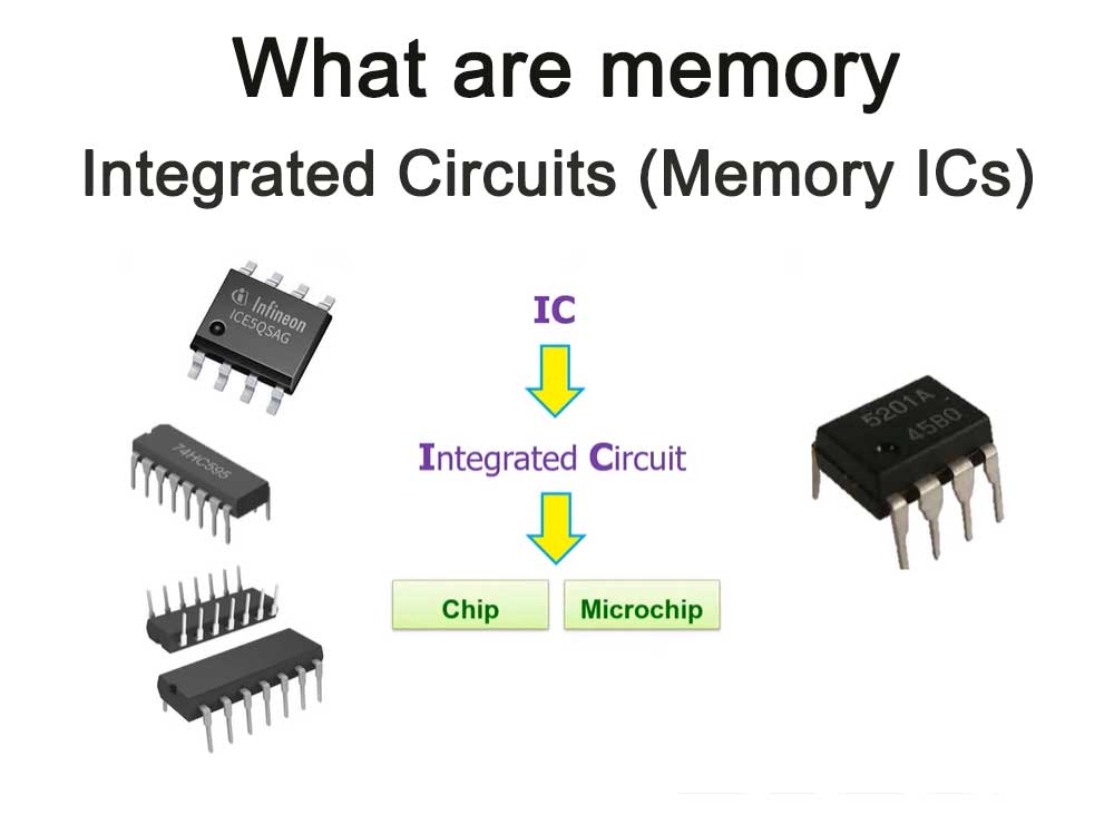
What is memory?

Memory is one of the most important components in the computer. It is the bridge between the program and the CPU.

All programs in the computer run in the memory, so the memory has a great impact on the computer. The memory is also called the main memory. Its function is to store the calculation data in the CPU and exchange it with external storage devices such as hard disks. data.

As long as the computer is running, the CPU will transfer the data that needs to be calculated to the main memory for calculation. When the calculation is completed, the CPU will transmit the results. The operation of the main memory also determines the stable operation of the computer.

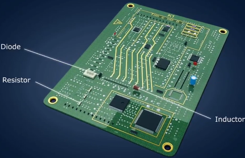
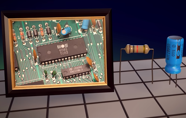
Physical structure of memory

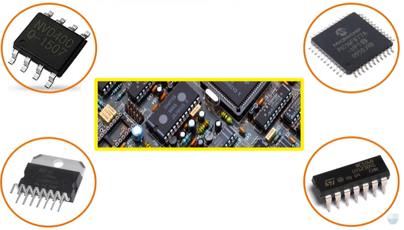
The interior of memory is composed of various IC circuits. There are many types of memory, but it is mainly divided into three types of memory:

Random access memory (RAM): The most important type of memory, meaning that data can be read from and written to. When the machine is turned off, the information in memory is lost.

Read-only memory (ROM): ROM can generally only be used to read data and cannot write data, but when the machine loses power, the data will not be lost.

Cache: Cache is something we often see. It is divided into level one cache (L1 Cache), level two cache (L2 Cache), and level three cache (L3 Cache). It is located between the memory and the CPU. , is a memory that reads and writes faster than memory. When the CPU writes data to memory, the data is also written to the cache. When the CPU needs to read data, it will read it directly from the cache. Of course, if the required data is not in the cache, the CPU will read the data in the memory.

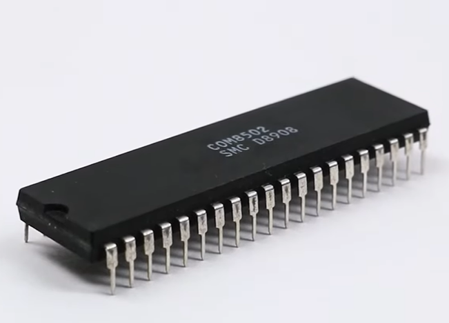
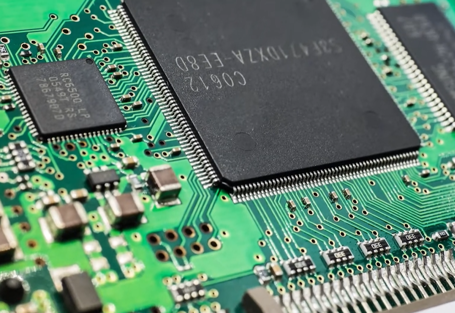
The memory IC is a complete structure. It also has power supply, address signals, data signals, control signals and IC pins for addressing to read and write data. Here is a virtual IC pin diagram:

Memory IC pin configuration structure diagram

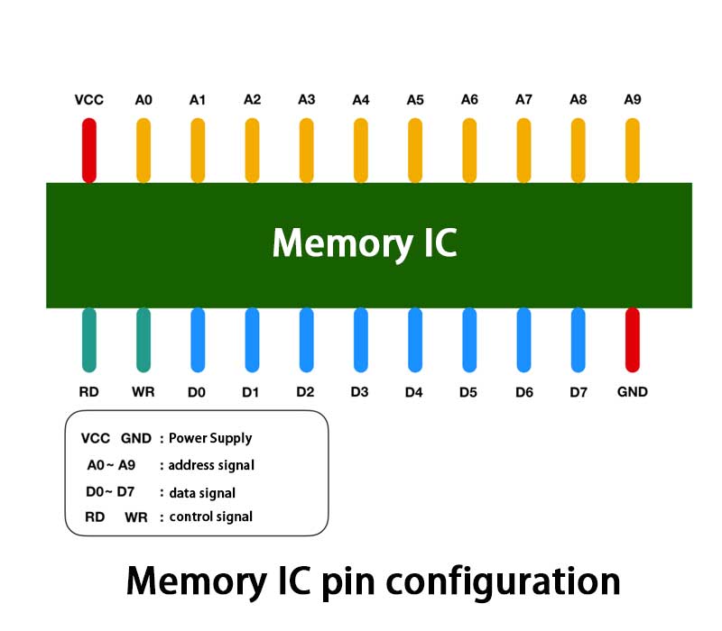
In the picture, VCC and GND represent the power supply, A0 – A9 are the address signal pins, D0 – D7 represent the control signal, RD and WR are good control signals. I use different colors to distinguish them, and connect the power supply to VCC and GND, you can pass 0 and 1 signals to other pins. In most cases, +5V means 1, and 0V means 0.

We all know that memory is used to store data, so how much data can be stored in this memory IC? D0 – D7 represent data signals, that is to say, 8 bit = 1 byte of data can be input and output at one time. A0 – A9 are ten address signals in total, which means that 00000 00000 – 11111 11111 can be specified, a total of 2 to the 10th power = 1024 addresses.

Each address stores 1 byte of data, so we can conclude that the capacity of the memory IC is 1 KB.

Memory reading and writing process

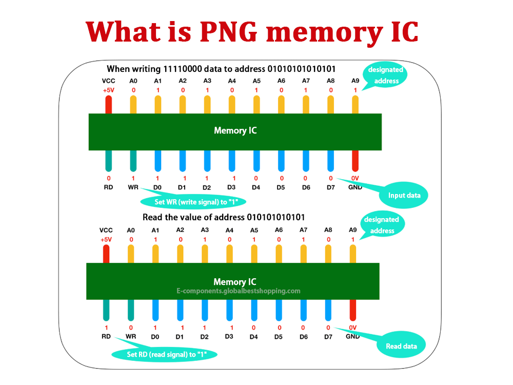
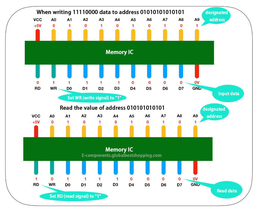
Let us focus on the process of reading and writing data by the memory IC! Let’s look at a model for writing and reading data to a memory IC

Reading and writing data from memory IC

What is PNG memory ic used for?

PNG Memory IC is a storage device used to store data, similar to a computer’s hard drive or a mobile phone’s memory. It uses the PNG (Portable Network Graphics) format to store data, usually in the form of a flash drive or memory card.

Specifically, PNG memory IC can be used in the following scenarios:

  1. Data backup and recovery: Back up important data to PNG memory IC, which can restore data when the data is lost or damaged.
  2. Storage and transmission: Similar to other storage devices, data such as files, pictures, videos, etc. can be stored in the PNG memory IC and transmitted when needed.
  3. Expanded storage space: For some devices, such as digital cameras, tablets, etc., PNG memory IC can be used as extended memory to increase the storage capacity of the device.
  4. Encryption and security: Some PNG memory ICs have encryption functions to protect the security and privacy of data.

In short, PNG memory IC is a storage device used to store and transmit data and has a wide range of application scenarios.

How about PNG memory stick?

PNG memory sticks refer to memory sticks using the PNG (Portable Network Graphics) format. However, in current computer hardware, PNG format memory sticks are not used because PNG is an image file format, not a hardware device for storing data.

The memory stick in a computer usually refers to RAM (Random Access Memory), which is a temporary memory in the computer used to store running programs and data. RAM formats and standards are dictated by the computer hardware industry, not image file formats.

Therefore, the issue of “PNG memory stick” is actually a misunderstanding or confusion. PNG is just an image file format, and it is two completely different concepts from the computer’s memory stick. Therefore, it is impossible to make a specific evaluation or comparison of the “PNG memory module” because it is not an actual hardware device.

What are the advantages of PNG memory ICs?

The advantages of PNG memory ICs may include the following aspects:

  1. Portability: PNG is a widely used image file format that can be easily opened and edited in various operating systems and software. Therefore, using PNG format memory cards or flash drives makes it easy to transfer and share data between different devices and software.
  2. Compatibility: PNG is a lossless compression format that can retain the complete quality of the image and avoid image distortion or quality degradation. This makes PNG memory ICs highly compatible and reliable when storing and transmitting high-definition images.
  3. Security: The PNG format supports transparency and alpha channels, allowing you to create images with complex backgrounds and transparency. This makes PNG memory ICs somewhat secure when storing and transmitting sensitive data, as data visualization and access rights can be better controlled.
  4. Efficiency: PNG is an efficient image file format that can reduce file size and storage space while ensuring image quality. This makes the PNG memory IC more efficient when storing large amounts of image data, saving storage resources and transmission costs.

It should be noted that the above advantages are only some possible aspects, and the specific advantages depend on the actual application scenarios and needs.

What are the disadvantages of PNG memory ICs?

Disadvantages of PNG memory ICs may include the following:

  1. Compatibility issues: Although PNG is a widely used image file format, there may be compatibility issues in some specific fields or software. For example, some older software or operating systems may not be able to correctly recognize or open PNG files.
  2. Insufficient animation support: The PNG format does not support animation effects. Compared with other dynamic image formats (such as GIF or MP4), it has limitations in expressing dynamic content.
  3. Relatively large file size: Compared with some other image formats (such as JPEG), the file size of the PNG format is usually larger, which may affect storage space usage and transmission efficiency.
  4. Transparency problem: Although PNG supports transparency settings, in some cases there may be problems with improper transparency processing or transparency not matching the background, which may affect the overall effect of the image.

It should be noted that the above disadvantages are only some possible aspects, and the specific disadvantages depend on the actual application scenarios and requirements. When choosing to use a PNG memory IC, you need to weigh its advantages and disadvantages based on actual needs.

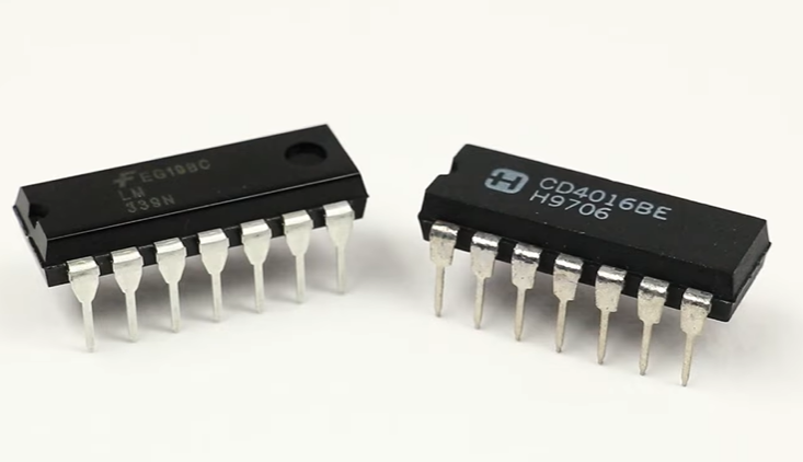
PNG Memory IC main types

There are two main types of PNG memory ICs: static random access memory (SRAM) and dynamic random access memory (DRAM).

SRAM is faster and more expensive than DRAM. DRAM is cheaper than SRAM, but slower.

What are the uses of PNG memory ICs?

PNG memory ICs are used in a variety of applications including:

  • Store code and data
  • Cached data
  • Provide storage capacity
  • Improve performance

PNG Memory ICs are used in mobile devices, computers and other electronic devices. They are used to store code, data, and other information required by the application. PNG memory ICs are also used to cache data to improve performance.

PNG What is the future of memory ICs?

The market for PNG memory ICs is expected to continue growing in the coming years. This is mainly due to the popularity of mobile devices and other electronic devices. PNG memory ICs will also benefit from the adoption of emerging technologies such as artificial intelligence and machine learning.

PNG memory IC manufacturer

  • Samsung Electronics
  • Micron Technology
  • Texas Instruments
  • Intel
  • Toshiba
  • Sony
  • Renesas Electronics
  • Fujitsu

Research and analysis of RGB memory IC

Research and analysis of RGB memory IC

RGB memory IC is a memory chip that uses RGB (red, green, and blue) color coding and is mainly used to store image and video data.

Compared with traditional memory chips, RGB memory ICs have higher storage capacity and faster reading and writing speeds, and can meet the needs of high-resolution and high-frame-rate video processing.

What is RGB memory IC?

RGB memory IC is a memory chip based on RGB color coding, mainly used to store image and video data. RGB color coding is a coding method that converts color information into three color values of red, green and blue.

It is widely used in the field of digital image and video processing. RGB memory IC uses this encoding method to store image and video data in the memory chip for subsequent processing and transmission.

Working principle

The working principle of RGB memory IC mainly involves three aspects: data encoding, storage and reading. First, image and video data are converted into RGB color-coded form and then stored in the memory chip. During the storage process, the data is divided into multiple data blocks, and each data block contains a certain number of pixel information.

IC chip - Working principle

The color information of each pixel is stored in the corresponding memory unit in the form of RGB color coding. When reading data, RGB color-coded data blocks are read from the corresponding memory unit as needed, and then decoded and synthesized to finally form complete image or video data.

Development History

The development of RGB memory ICs has gone through multiple stages. The earliest RGB memory ICs were mainly used in professional-level image and video processing equipment. With the development of technology and market demand, RGB memory ICs have gradually become popular in consumer electronics products, such as smartphones, tablets, etc. At present, RGB memory IC has become one of the indispensable memory chips in the field of digital image and video processing.

Brand and manufacturer

There are currently many manufacturers on the market that produce and supply RGB memory ICs, such as Samsung, Micron, Hynix, etc. These manufacturers have advanced production technology and equipment and can provide RGB memory ICs of different specifications and capacities to meet the needs of different fields and applications.

IC on the circuit board

RGB memory IC type

According to different classification standards, RGB memory ICs can be divided into many types. According to different storage media, it can be divided into types such as DRAM and SRAM; according to different packaging forms, it can be divided into plug-in type, SMD type and BGA packaging type. In addition, according to different application requirements, the capacity and speed of RGB memory ICs also vary to meet the needs of different fields and applications.

In short, RGB memory IC, as a high-performance memory chip, has broad application prospects in the field of digital image and video processing. With the continuous advancement of technology and the growing market demand, the performance of RGB memory ICs will continue to improve, and the application fields will continue to expand.

Research and analysis on RGB memory IC

Research and analysis on RGB memory IC

Research and analysis on RGB memory ICs mainly focus on the following aspects:

Performance study

Mainly studies performance indicators such as read and write speed, storage capacity, and power consumption of RGB memory ICs, as well as the impact of these performance indicators on digital image and video processing efficiency. At the same time, the stability and reliability of RGB memory ICs are tested and analyzed to ensure their stability and reliability in different application scenarios.

Electronic Component

Applied research

Mainly studies the application effects of RGB memory IC in different fields and different application scenarios, including digital cameras, camcorders, smartphones, tablets and other consumer electronics products, as well as professional-level image and video processing equipment. In addition, the application prospects and potential of RGB memory ICs in emerging technology fields such as artificial intelligence and the Internet of Things are studied.

Technology research

Mainly researches the key technologies involved in RGB memory IC, such as data encoding, storage and reading technology, process technology, packaging technology, etc. At the same time, the development trends and future technology development directions of RGB memory ICs are discussed and researched to promote the continuous progress and innovation of RGB memory IC technology.

Research and analysis of RGB memory IC

Market research

Mainly studies the market demand, market size, market competition pattern, etc. of RGB memory ICs. Analyze the market development trends and future market potential of RGB memory ICs, and provide market analysis and decision-making support for manufacturers and related companies.

Compatibility and standards studies

Research and formulate the compatibility and standards of RGB memory ICs to ensure the compatibility and interoperability of RGB memory ICs between different platforms and application software. At the same time, we will promote the standardization process of RGB memory ICs and promote the widespread application and development of RGB memory ICs.

Memory IC Brand Suppliers and Manufacturers

To sum up, the research and analysis of RGB memory IC needs to be carried out from many aspects, including performance research, application research, technology research, market research, compatibility and standard research, etc. Through in-depth research and analysis of these aspects, we can better understand the development trends and application prospects of RGB memory ICs, and provide references for future technological development and applications.

RGB memory IC FAQs

What are the advantages of RGB memory ICs?

The advantages of RGB memory ICs are their high storage capacity and read and write speeds. It can quickly store and read large amounts of image and video data to meet the needs of high-resolution, high-frame-rate video processing. In addition, RGB memory ICs also have good stability and reliability, ensuring data accuracy and integrity.

What are the main application scenarios of RGB memory ICs?

RGB memory ICs are mainly used to store and transmit image and video data. Common application scenarios include digital cameras, camcorders, smartphones, tablets and other consumer electronics, as well as professional-level image and video processing equipment.

How to choose the right RGB memory IC?

Choosing a suitable RGB memory IC requires consideration of multiple factors, such as capacity, speed, power consumption, packaging form, etc. At the same time, application scenarios and requirements also need to be considered, such as image and video resolution, frame rate, etc. It is recommended to choose well-known brands and manufacturers, and carefully read product specifications and technical information to ensure that you choose a suitable RGB memory IC.

What is the development trend of RGB memory IC?

With the continuous advancement of technology and the growing market demand, the development trend of RGB memory IC is high capacity, high speed, low power consumption and multi-functionality. At the same time, with the development of 5G communication technology, RGB memory IC will also be used in more wireless communication devices to achieve more efficient data storage and transmission.

What are memory integrated circuits (Memory ICs)

What are memory integrated circuits (Memory ICs)

Memory ICs are integrated circuits used to store data. They are an important component in the field of microelectronics and are widely used in computers, communications, consumer electronics and other fields.

Memory integrated circuits can be divided into various types according to different classification standards. The following is a detailed introduction to memory integrated circuits:

Overview

A memory integrated circuit integrates a large number of memory cells on a chip to realize data storage and reading functions.

They are usually made of semiconductor materials and utilize the switching properties of semiconductor devices to achieve data storage. Memory integrated circuits have the characteristics of high speed, large capacity, and low power consumption, and are an important part of modern electronic systems.

What is a memory integrated circuit memory ic explain

Classification

According to storage media

Depending on the storage media used, memory integrated circuits can be divided into two categories: volatile memory and non-volatile memory.

Volatile memory refers to memory that loses data after a power outage, such as random access memory (RAM) and cache memory (CACHE). This type of memory is mainly used for computer internal memory, providing fast read and write speeds and large data storage capacity.

Application of integrated circuits (IC) in mobile phones

Non-volatile memory refers to memory that can still retain data after power is turned off, such as read-only memory (ROM), electrically erasable programmable read-only memory (EEPROM) and flash memory (Flash Memory). This type of memory is mainly used for external memory of computers, such as hard disks, USB flash drives, etc., providing long data retention time and high data storage density.

According to the degree of integration

According to the level of integration, memory integrated circuits can be divided into small-scale integrated circuits (SSI), medium-scale integrated circuits (MSI), large-scale integrated circuits (LSI) and very large-scale integrated circuits (VLSI). With the continuous development of technology, integrated circuits are becoming more and more integrated, which can achieve higher data storage density and faster reading and writing speeds.

According to manufacturing process

According to different manufacturing processes, memory integrated circuits can be divided into thin film integrated circuits and thick film integrated circuits. Thin film integrated circuit refers to the integration of circuit components and wires on semiconductor materials, and is usually used to manufacture large-scale and ultra-large-scale integrated circuits. Thick film integrated circuits refer to the integration of circuit components and wires on ceramics or other insulating materials, and are usually used to manufacture medium- and small-scale integrated circuits.

Working principle

The working principle of memory integrated circuits is mainly to store and read data through the switching characteristics of semiconductors. In volatile memory, each memory cell usually consists of a transistor and a small capacitor. The source and drain of the transistor are connected together as the input/output terminal of the memory cell. One end of the small capacitor is connected to the gate of the transistor, and the other end is connected to ground. When a small capacitor is charged, the threshold voltage of the transistor changes, causing the transistor to be in different switching states to enable data writing. When reading data, it is determined whether the data stored in the memory cell is 0 or 1 by reading the switching state of the transistor.

In non-volatile memory, each memory cell usually consists of a floating-gate transistor. Floating-gate transistors have a polysilicon gate that stores electrons. When electrons enter the floating gate, the threshold voltage of the transistor changes, allowing data to be written. When reading data, it is determined whether the data stored in the memory cell is 0 or 1 by reading the switching state of the transistor.

Application areas

Memory integrated circuits are widely used in various fields, including computers, communications, consumer electronics, etc. In the computer field, memory integrated circuits are mainly used in the manufacture of internal memory and external memory, such as DRAM, SRAM, Flash Memory, etc.

In the field of communications, memory integrated circuits are mainly used for storage and control of signal processing and data transmission, such as flash memory in mobile phones and DRAM in routers.

memory integrated circuits

In the field of consumer electronics, memory integrated circuits are mainly used for storage and control of audio and video processing, game control, GPS navigation and other equipment.

Memory IC list

What are the classifications of memory ICs? The storage IC list includes the following types:

  1. Random access memory (RAM): including static random access memory (SRAM) and dynamic random access memory (DRAM).
  2. Read-only memory (ROM): including mask read-only memory (Mask ROM), programmable read-only memory (PROM), erasable programmable read-only memory (EEPROM) and flash memory (Flash Memory), etc.
  3. Non-volatile memory: such as ferroelectric random access memory (FRAM) and magnetic random access memory (MRAM).

These storage ICs have different characteristics and application scenarios. Choose the appropriate storage IC type according to actual needs.

Top 10 Memory IC Brand Suppliers and Manufacturers

What brands of memory IC are there? There are many brands of memory ICs, including but not limited to the following:

  1. Micron: One of the world’s largest manufacturers of semiconductor storage and imaging products. Its main products include DRAM, NAND flash memory and NOR flash memory.
  2. Samsung: One of the world’s largest semiconductor manufacturers, its memory IC products include DRAM, NAND flash memory, etc.
  3. SK Hynix: One of the world’s second largest semiconductor manufacturers, its main products include DRAM and NAND flash memory.
  4. Kingston: One of the world’s largest independent memory module manufacturers, its products include DRAM and flash memory.
  5. Crucial: It is a brand of Micron Technology and mainly sells storage products such as solid-state drives and memory sticks.
  6. G.Skill: Focus on the development and promotion of high-end computer memory products, providing high-speed and stable memory solutions.
  7. Corsair: Provides high-quality memory modules, solid-state drives, power supplies and gaming peripherals.
  8. Adata: Provides various types of memory products, including DDR, DDR4, SSD and mobile device memory.
  9. PNY: Memory products launched by the American PNY Technology Company, including memory modules of various specifications and capacities.
  10. Transcend: Focus on the development and promotion of high-speed, high-quality memory modules and flash drives.

In addition, brands such as SanDisk, Kingmax, and Apacer also provide memory IC products. Each of these brands has its own characteristics and advantages, and you can choose according to actual needs.

What is a memory chip?

A memory chip, also called a memory particle, is a semiconductor chip that is mainly used to store temporary information and data required for program execution. It stores data in units with addresses through integrated circuits, and has the characteristics of fast reading and writing speed and large capacity. Memory chip is an important part of the computer system. It is used to temporarily store information such as programs, data, and operating systems. It is the basis for the normal operation of the computer.

The principle of memory chips is to store and read data through changes in binary signals. The memory chip uses bits as the smallest unit and combines a series of bits to form a binary code to store and read data. In a memory chip, data is organized in an address space, and each data unit has a unique address. By addressing the unit, the CPU can access any data unit in the memory.

The structure of a memory chip usually consists of memory cells, address lines and control lines. The storage unit is the most basic unit in the memory and is used to store binary data bits; the address line is used to transmit the memory address information sent by the CPU; the control line is used to control and synchronize read and write operations. Generally, memory chips are composed of multiple storage units, each of which includes a certain number of binary data bits, an address pin and one or more control pins.

The function of the memory chip is to store information such as programs, data, and operating systems, and is the basis for the normal operation of the computer. In mobile devices such as mobile phones, memory chips play a similar role, storing temporary data and related resources needed to run applications.

In addition, memory chips can be divided into many types according to different classification standards. For example, according to different storage media, it can be divided into DRAM and SRAM types; according to different packaging forms, it can be divided into plug-in type, SMD type and BGA packaging type. Different types and specifications of memory chips have different performance indicators and application scenarios, so choosing a suitable memory chip is crucial to the performance and stability of the entire system.

Which one is better, Nicknix or SKHynix?

Regarding the question of which one is better, Nicknix or SK Hynix, it is difficult to make a direct comparison due to their different positioning and applications in the memory IC field.

Nicknix is a brand that focuses on memory modules and solid-state drives. Its product line includes memory modules of various specifications and capacities and various types of solid-state drives. The brand’s products use high-quality components and materials to ensure the stability and reliability of its products. However, there is relatively little information about Nicknix’s specific product performance and user reviews, making it difficult to fully evaluate its products.

SK Hynix is one of the world’s leading semiconductor manufacturers. Its memory IC products include DRAM and NAND flash memory, which are widely used in computers, smartphones and other electronic devices. The company’s products are known for their high performance, high reliability and high stability and are widely used in various fields. In addition, SK Hynix also has advanced production technology and R&D capabilities, and continues to launch innovative products and technologies.

Therefore, it is impossible to simply judge whether Nicknix or SK Hynix is better. Users can choose brands and products that suit them based on their needs and budget. When choosing a memory IC, it is recommended to consider the performance, reliability, stability and compatibility of the product, and also pay attention to matching it with your own computer hardware and other components.

Memory ICs FAQs

How does a memory integrated circuit work?

The working principle of memory integrated circuits mainly uses the switching characteristics of semiconductors to store and read data. In volatile memory, each memory cell usually consists of a transistor and a small capacitor. By charging or discharging a small capacitor, the threshold voltage of the transistor can be changed, thereby controlling its switching state and enabling data writing and reading. In non-volatile memory, each memory cell usually consists of a floating-gate transistor. By injecting or expelling electrons into the floating gate, the threshold voltage of the transistor can be changed, allowing long-term data retention.

What types of memory integrated circuits are there?

There are many types of memory integrated circuits, including but not limited to the following:
RAM (Random Access Memory): A type of volatile memory that allows random reading and writing of data, with high-speed reading and writing speeds and large data storage capacity.
ROM (read-only memory): a non-volatile memory that can only read data but cannot write data. It is often used to store firmware programs and basic data.
Flash Memory: A non-volatile memory that achieves long-term storage of data through charge storage technology. It is widely used in USB flash drives, SSD solid state drives and other fields.
EEPROM (Electrically Erasable Programmable Read-Only Memory): A non-volatile memory that allows users to erase and rewrite data while powered on. It is often used for parameter storage of microcontrollers and backup of user data.

What is the development trend of memory integrated circuits?

With the continuous advancement of technology and increasing application requirements, the development trends of memory integrated circuits mainly include the following aspects:
High integration: Continuously reduce the size of transistors and increase integration to achieve higher data storage density and faster reading and writing speeds.
Low power consumption: Optimize circuit design and manufacturing process to reduce power consumption and extend the service life of the equipment.
Improved reliability: By improving materials, processes and circuit design, the reliability of the memory is improved to ensure the long-term preservation and stability of data.

What is a flash memory chip?

Flash memory chip is a non-volatile memory chip made using flash memory technology. It is usually made of Flash Memory. Flash memory chips have the characteristics of data not disappearing after power outage, large capacity, safe and reliable, fashionable and fashionable, etc., and are an ideal portable storage tool. It can carry heavy loads of stored data and system software, and is suitable for fields such as embedded systems and electronic products. Compared with traditional disk drives, flash memory chips have no moving parts, are more durable and effectively reduce signal interference and power consumption. Flash memory chips usually use flash memory storage media and universal serial bus (USB) interfaces, which are lightweight, delicate, easy to use, and easy to carry. The storage speed of flash memory chips also varies depending on the capacity and number of pages. It usually only supports reading data, which is very fast and suitable for storing large-capacity data.

What are memory integrated circuits (Memory ICs)?

Memory ICs are integrated circuits used to store data. They use the switching characteristics of semiconductors to store and read data, and have the characteristics of high speed, large capacity, and low power consumption. Memory integrated circuits can be divided into volatile memories and non-volatile memories, which are widely used in computers, communications, consumer electronics and other fields.

What are the application scenarios of memory integrated circuits?

Memory integrated circuits are widely used in various fields, including but not limited to the following:
Computer field: used to manufacture internal memory and external memory, such as DRAM, SRAM, Flash Memory, etc., to provide high-speed data storage and access functions.
Communication field: used for storage and control of signal processing and data transmission, such as flash memory in mobile phones, DRAM in routers, etc., to achieve fast reading, writing and long-term storage of data.
Consumer electronics field: used for storage and control of audio and video processing, game control, GPS navigation and other equipment, providing stable and reliable data storage and access capabilities.
Other fields: such as aerospace, medical, smart home, etc., used for data storage and processing to achieve specific functions and uses.

What is random access memory?

Random access memory (RAM) is a type of computer memory that can directly access any storage location and read and write data quickly. The characteristic of RAM is data volatility, that is, the stored data will be lost when the power is turned off. RAM can be divided into types such as dynamic random access memory (DRAM) and static random access memory (SRAM). In computer systems, RAM usually serves as a temporary data storage medium for the operating system or other running programs.

What is non-volatile memory?

Non-volatile memory (NVM) is a type of computer memory. Its characteristic is that the stored data will not disappear when the current is turned off, that is, the data will not be lost due to power outage. Non-volatile memory usually refers to storage in semiconductor memory chips, storing data in floating gate memory cells composed of floating gate MOSFETs (Metal Oxide Semiconductor Field Effect Transistors).
The main types of non-volatile memory are: ROM (read-only memory), PROM (programmable read-only memory), EAROM (electrically rewritable read-only memory), EPROM (erasable programmable read-only memory) and EEPROM ( Electrically erasable programmable read-only memory), etc. In addition, Flash Memory is also a kind of non-volatile memory, which can achieve fast erasure and programming of data.
The advantage of non-volatile memory is that data is not lost due to power outages, so it can store data for a long time. In addition, non-volatile memory has high performance and can read and write data quickly. Due to these advantages, non-volatile memory is widely used in various fields, such as computer systems, communication equipment, consumer electronic equipment, etc.

What is a memory ic used for?

Memory ICs are primarily used for data storage and are key components in computers, smartphones, and many other electronic devices. The high-speed random access characteristics of memory ICs enable it to read and write data quickly, thereby improving system performance. In addition, memory ICs have other applications, such as being used in microprocessors to parse and execute program instructions, in operational amplifiers to amplify signals, and in various control and management circuits to implement various functions. In summary, memory ICs are an integral part of modern electronic systems and play an important role in various applications.

What is a central processing unit (CPU)?

The central processing unit (CPU) is the core component of the computer system. It is used to execute instructions and control various activities of the computer. It is the “brain” of the computer system. The functions of the CPU include program control, operation control, time control and data processing. Since its creation, CPU has made great progress in logical structure, operating efficiency and function extension.

What is SSI?

SSI (Server Side Includes) is a server-based web page production technology, usually used to dynamically generate web page content. By using SSI instructions, text, graphics, or application information can be included into web pages, and this information can be dynamically generated and updated on the server side.
Using SSI technology, instructions can be inserted into an HTML document that instruct the web server to insert certain content into the page before sending it to the client. For example, you can use SSI directives to include time/date stamps, copyright notices, or forms for customers to fill out and return.
In addition, SSI also has some advanced functions, such as including files, executing shell and CGI script programs, etc. By using include files, you can put the content into a separate file and then just call that file in the HTML document, rather than typing the content into each file. This makes it easy to manage and maintain web content.
In general, SSI is a powerful and flexible web page production technology that can help developers dynamically generate and update web page content on the server side, improving the performance and maintainability of the website.

What is NANDFLASH chip?

NAND Flash chip is a type of flash memory chip that uses NAND storage logic and is non-volatile and the stored data remains unchanged for a long time. It adopts non-linear macrocell mode internally, providing a cheap and effective solution for the realization of solid-state large-capacity memory. In addition, NAND Flash memory uses floating-gate transistors and can store information without power. All circuits rely on some kind of energy to create a difference in charge across the battery. This energy forces electrons through the gate. The floating gate system of NAND flash memory works by using a second gate to collect and store electrons as they pass through the battery. Capturing some electrons, this allows the electrons stuck to the floating gate to stay in place without voltage, allowing the chip to continue storing the next value regardless of whether there is a power connection.
In general, NAND Flash chip is a large-capacity, high-reliability memory chip that is widely used in computers, consumer electronics, security equipment, automotive electronics and other fields.

How much does it cost to store an IC?

Storage IC prices vary depending on model, specification, brand and supplier. At the same time, factors such as market supply and demand, production costs, etc. will also affect the price of storage ICs.
Generally speaking, the price of storage IC ranges from tens of yuan to tens of thousands of yuan. For example, the price of some common NOR Flash chips with a capacity of 1GB is around 200~400 yuan, while the price of some large-capacity and high-performance storage ICs, such as solid-state drives (SSDs), is higher. An SSD with a capacity of 1TB The price ranges from 500 to 1,000 yuan. Of course, the specific price still needs to be negotiated with the supplier based on actual demand and purchase volume.

What are McAfee McAfee ICs?

McAfee is a network security company founded in 1987 and headquartered in Santa Clara, California, USA. As a leading cybersecurity company, McAfee provides a wide range of cybersecurity solutions, including anti-virus software, network intrusion detection systems, and data encryption solutions.
Regarding “McAfee ICs”, I cannot provide relevant information. You can provide more background information or context about “McAfee ICs” so that I can better answer your question.

Principles of insertion methods for electronic components

Principles of insertion methods for electronic components

The principle of insertion method of electronic components is an important part of the electronic assembly process, involving many aspects such as circuit board design, component selection and layout, and the efficiency of the production process.

The following is a detailed introduction to the principles of electronic component insertion.

Principles of component insertion

  1. Polarity of components: When inserting components, the polarity of each component must be clear based on the circuit diagram and component specification table, and the correct direction must be ensured for installation.
  2. Marking of components: All installed components must be clearly marked. These markings include component numbers, specifications, directions, etc. to facilitate subsequent debugging and maintenance.
  3. Layout of components: The layout of components should be as uniform and symmetrical as possible in accordance with the requirements of circuit design to improve the overall aesthetics and reduce thermal stress caused by uneven heat distribution.
  4. Fixing of components: Components should be fixed on the PCB board by welding, mechanical clamping, gluing, etc. During the fixing process, avoid applying excessive pressure or torque to the components to avoid damage.
  5. Spacing of components: The spacing between components should be determined according to the requirements of the circuit and the production process. Proper spacing ensures the electrical performance of the circuit board and the operability of the production process.
  6. Identification of components: Components should be clearly marked, including component numbers, specifications, directions, etc., to facilitate subsequent debugging and maintenance.

Choice of insertion method

Principles of insertion methods for electronic components
  1. Manual insertion and automatic insertion: According to the requirements of production scale and automation level, you can choose manual insertion or automatic insertion. Manual insertion is more flexible and suitable for small batch production and maintenance; automatic insertion is more efficient and suitable for mass production.
  2. Direct plug-in and surface mount: There are two methods of component insertion: direct plug-in and surface mount. In-line components can be directly inserted into the holes of the PCB board; surface mount components are directly attached to the surface of the PCB board. Surface mounting has the advantages of small size, light weight, and high reliability, but the manufacturing cost is high.
  3. Ordinary plug-in and special plug-in: For some circuit boards with special requirements, such as high-density and high-reliability aerospace fields, special plug-in methods are required, such as vertical installation, flip-chip welding, etc.
Electronic component symbols and representation methods

Principles and key points of instrumentation

  1. Ensure electrical performance: When inserting components, ensure that the electrical performance of the circuit board is met. For example, for some high-frequency signal lines, avoid excessively long traces or right-angle bends to reduce signal loss and noise.
  2. Heat dissipation design: For some high-power components, heat dissipation issues need to be considered. Good heat dissipation can be ensured by properly arranging the radiator or increasing the spacing between components.
  3. Prevent electromagnetic interference: When inserting components, electromagnetic interference issues should be considered. The impact of electromagnetic interference on circuit performance can be reduced by rationally arranging components and adding shielding measures.
  4. Convenient maintenance and testing: When inserting components, subsequent maintenance and testing should be considered. Test points can be set up and clearly marked to facilitate maintenance personnel for inspection and repair.
  5. Consider manufacturing costs: On the premise of meeting performance requirements, manufacturing costs should be reduced as much as possible. This can be achieved by optimizing circuit design, selecting appropriate components and insertion methods.

Practical application case analysis

In actual applications, it is necessary to choose the appropriate insertion method according to specific application scenarios and needs. For example, for some aerospace fields with high reliability requirements, special insertion methods can be used to ensure the performance and reliability of circuit boards; for some consumer electronics products, automated insertion methods can be used to improve production efficiency.

To sum up, the principle of insertion method of electronic components is an important part of the electronic assembly process. During the plug-in process, certain principles and key points need to be followed, and multiple factors such as electrical performance, reliability, and manufacturing cost must be comprehensively considered. The correct insertion method can ensure the performance and reliability of the circuit board, improve production efficiency, and reduce maintenance costs.

Frequently Asked Questions on the Principles of Inserting Electronic Components

Why do we need to clean electronic components before inserting them?

Before electronic components are inserted, the printed circuit board must be cleaned to remove impurities such as dirt, dust, and oxides on the surface. These impurities may cause short circuits, open circuits on the circuit board, or affect the stability of components.

Why can’t the pins of electronic components be bent?

The pins of electronic components cannot be bent, because bent pins may short-circuit or have poor contact with adjacent pins, causing circuit failure. In addition, lead bending can affect the mechanical properties and reliability of components.

How to avoid damage to electronic components during the insertion process?

When inserting electronic components, ensure that the insertion direction is correct and the force is moderate, and avoid using brute force. At the same time, the principles of first small then large, first low then high, first light then heavy should be followed to avoid damage to other installed components.

How to ensure the stability of electronic component insertion?

In order to ensure the stability of electronic component insertion, the insertion should be carried out according to a reasonable layout and arrangement to ensure that each component can be firmly fixed on the printed circuit board. At the same time, an appropriate amount of solder should be used and the welding quality should be ensured to prevent problems such as desoldering and virtual soldering.

How to identify the quality of electronic components?

Before insertion, the quality of electronic components should be checked. Detection can be done through visual inspection, measurement and testing. If necessary, use a magnifying glass or microscope for a more detailed inspection. If there are any damaged or unqualified components, they should be replaced in time.

Detection solution for low voltage sensor module

Detection solution for low voltage sensor module

The low-voltage sensor module testing solution is a set of systematic and standardized testing processes, aiming to ensure that the module performance meets standards and has high reliability.

Through multiple tests such as environmental adaptability testing and electrical performance testing, the various indicators of the module are comprehensively evaluated to provide Provide a strong basis for product optimization.

Introduction

With the continuous development of industrial automation and intelligence, low-voltage sensor modules have been widely used in various equipment and systems.

In order to ensure the performance and quality of low-voltage sensor modules, it is crucial to develop an effective detection program.

This solution aims to conduct a comprehensive and accurate detection of the low-voltage sensor module to ensure its normal and stable operation.

Low voltage module design on PCB

Testing purpose

  1. Verify whether the performance indicators of the low-voltage sensor module meet the design requirements;
  2. Test the performance of the low-voltage sensor module under actual working conditions;
  3. Discover potential problems and failures of low-voltage sensor modules and reduce product repair rates;
  4. Provide a basis for quality assessment and continuous improvement of low-voltage sensor modules.

Detection content and methods

Appearance inspection

Observe the appearance of the low-voltage sensor module and check whether there is damage, deformation, stains, etc., and whether the markings are clear and accurate.

Dimensional measurement

Use measuring tools to measure the critical dimensions of the low-voltage sensor module to ensure that it meets the design requirements.

Electrical performance test

Input voltage range test

Test whether the low-voltage sensor module can work normally within the specified input voltage range;

Output accuracy test

Pass the standard signal source input signal, measure the output signal of the low-voltage sensor module, and calculate its accuracy;

Response time test

When the input signal changes, measure the time it takes for the output signal of the low-voltage sensor module to change.

Environmental adaptability test

Temperature test

Test the performance of the low-voltage sensor module under different temperature conditions (such as -20°C, 25°C, 65°C, etc.);

Humidity test

Test the performance of the low-voltage sensor module under different humidity conditions;

Vibration test

Conduct a vibration test on the low-voltage sensor module to detect its anti-vibration performance.

Functional test

According to the specific functions of the low-voltage sensor module, simulate the actual working scenario and test its various functions.

Reliability test

Test the reliability of the low-voltage sensor module through accelerated life tests, fatigue tests and other methods.

Testing process and steps

ZMPT101B 250V AC Voltage Sensor with Arduino, Voltage Monitoring
  1. Prepare testing equipment and environment to ensure compliance with testing requirements;
  2. Carry out appearance inspection and dimensional measurement, and record the inspection results;
  3. Conduct electrical performance tests and record various parameter indicators;
  4. Conduct environmental adaptability testing and record performance;
  5. Conduct functional tests to verify the normality of various functions;
  6. Conduct reliability testing to evaluate product life and reliability;
  7. Analyze and evaluate the test results and form a test report;
  8. According to the test report, unqualified products are processed, and qualified products are marked and stored in the warehouse.
Semiconductor device design - electronic component circuit diagram design

Test report and summary

After completing the inspection of the low-voltage sensor module, a detailed inspection report should be prepared. The report should include the following:

  1. Testing purposes and requirements;
  2. Test content and methods;
  3. Detection process and steps;
  4. Test results and analysis;
  5. Conclusion and recommendations.

Through the implementation of this solution, the low-voltage sensor module can be comprehensively and accurately tested to ensure that its performance and quality meet the requirements.

At the same time, this solution can also provide basis and suggestions for the continuous improvement and optimization of low-voltage sensor modules.

In practical applications, the solution can be adjusted and optimized according to specific circumstances to better meet actual needs.

USING A SYSTEM-ON-MODULE FOR EMBEDDED SYSTEMS DESIGN

What are the commonly used testing equipment for low-voltage sensor modules?

Commonly used testing equipment for low-voltage sensor modules include the following:

  1. Signal source: used to provide standard signals to test the output accuracy and response time of the low-voltage sensor module.
  2. Oscilloscope: used to measure and observe the output signal of the low-voltage sensor module to evaluate its performance.
  3. Power supply: Provide stable DC or AC power to test the performance of the low-voltage sensor module under different input voltages.
  4. Environmental chamber: used to simulate different temperature and humidity environments for environmental adaptability testing.
  5. Vibration table: used to simulate a vibration environment to test the anti-vibration performance of the low-voltage sensor module.
  6. Data acquisition and analysis system: used to collect and analyze test data of low-voltage sensor modules in order to quantitatively evaluate their performance.
  7. Calibration equipment: used to calibrate testing equipment and tools to ensure the accuracy and reliability of testing results.

These devices are commonly used tools in low voltage sensor module testing, and which device is used depends on the testing needs and requirements.

When selecting testing equipment and tools, ensure that their accuracy, reliability and applicability meet the testing requirements.

What testing tools need to be included in the testing solution for low-voltage sensor modules?

The detection solution for the low-voltage sensor module needs to include the following detection tools:

  1. Voltage test tool: such as a multimeter, used to measure whether the output voltage of the low-voltage sensor module is within the normal range.
  2. Current testing tools: such as ammeters, used to test whether the output current is normal and whether it meets the relevant parameters of the sensor.
  3. Internal resistance test tool: such as a multimeter or independent resistance meter, used to test whether the output resistance of the low-voltage sensor module is correct and stable.
  4. Environmental adaptability testing equipment: such as temperature chambers, humidity chambers and shaking tables, etc., used to simulate different environmental conditions and test the performance of low-voltage sensor modules.
  5. Signal source and oscilloscope: used to provide standard signals and measure the output signal of the low-voltage sensor module to evaluate its accuracy and response time.
  6. Calibration equipment: used to calibrate testing equipment and tools to ensure the accuracy and reliability of testing results.
Chip voltage module design - What testing tools need to be included in the testing solution for low-voltage sensor modules?

These tools are commonly used equipment in low-voltage sensor module testing. According to the specific testing needs and requirements, the corresponding equipment and tools can be selected for testing.

When selecting testing tools, ensure that their accuracy, reliability and applicability meet the testing requirements.

Low voltage sensor module testing FAQs

What is a low voltage sensor module?

The low-pressure sensor module is an electronic component used to measure low-voltage, weak electrical signals. It can sense pressure changes of liquids, gases, solids and other substances and convert them into electrical signal output.

Why test the low voltage sensor module?

Low-voltage sensor modules are widely used in industrial automation and intelligence. It is crucial to detect their performance and quality to ensure their normal and stable operation, reduce product repair rates, and provide a basis for continuous improvement.

How to conduct electrical performance testing of low voltage sensor modules?

Electrical performance testing includes input voltage range testing, output accuracy testing, response time testing, etc. Input the signal through the standard signal source, measure the output signal of the low-voltage sensor module, calculate its accuracy, and observe the response time.

What does the low-voltage sensor module detect?

The testing content of low-voltage sensor modules mainly includes appearance inspection, dimensional measurement, electrical performance testing, environmental adaptability testing and functional testing, etc.

What does environmental suitability testing mean for low-voltage sensor modules?

The environmental adaptability test includes temperature test, humidity test and vibration test, etc. It is designed to detect the performance of the low-voltage sensor module under different environmental conditions to ensure that it can work normally in various environments.

How to evaluate the reliability of low voltage sensor modules?

Test the performance of the low-voltage sensor module under different stress conditions and evaluate its reliability through accelerated life tests, fatigue tests and other methods.

What issues should be paid attention to when testing low-voltage sensor modules?

During the testing process, you need to pay attention to preventing overloading, preventing static electricity, ensuring good grounding, etc. to ensure the accuracy and reliability of the testing results. At the same time, relevant safety regulations and operating procedures should be followed to ensure the safety of personnel and equipment.

Study the power module in the embedded drive

Study the power module in the embedded drive

Research on power modules in embedded drives focuses on improving their energy efficiency, stability and lifespan to adapt to changing application requirements and promote energy conservation, emission reduction and system performance optimization.

Embedded discussion

With the rapid development of technology, the application of embedded systems in various fields is becoming more and more widely used, such as smart homes, industrial control, medical equipment, etc.

As an important part of the embedded system, the power module provides a stable energy source for the entire system, and its performance directly affects the stability and reliability of the entire system.

Therefore, in -depth research on the power module in embedded drivers has important theoretical and practical significance.

Overview of the power module in the embedded drive

Assembling electronic components on embedded PCB board - Overview of the power module in the embedded drive

The power module is the core part of the embedded drive, which is mainly responsible for converting the input power energy to the voltage and current suitable for embedded systems. It usually includes a rectifier circuit, filter circuit, voltage voltage circuit and other parts, which can realize functions such as voltage conversion, stability and protection.

Infineon power driver module

The performance indicators of the power module mainly include efficiency, power density, and reliability. Among them, the efficiency determines the energy conversion efficiency of the power module, and is an important indicator of the performance of the power module. The power density reflects the performance of the volume and weight of the power module; reliability is an important thing for the power module to run stable for a long time. Assure.

Power module design in embedded drive

The design of the power module requires comprehensive consideration of system requirements, electrical characteristics, and heat design. During the design process, the input and output voltage, current and other parameters of the power module need to be determined according to the maximum power consumption and voltage requirements of the system. At the same time, it is also necessary to consider the requirements of the efficiency, power density, and reliability of the power module to ensure that the power module can meet the long -term stable operation of the system.

HybridPACK™ Drive | Power modules for main inverter applications | Infineon

In addition, in order to improve the reliability of the power module, a series of optimization measures are needed, such as choosing high-quality electronic components, optimizing circuit design, and strengthening heat dissipation design.

How does the power module in the embedded driver be designed with the power module

In the cooling design of the power module in the embedded drive, the main consider how to effectively export the heat from the power module and reduce its working temperature to ensure the stable operation of the power module and extend its service life. Here are some points of some cooling design:

  1. Understand the heat source: First of all, you need to understand the main thermal sources in the power module, such as power semiconductors, inductors and capacitors. These components generate a lot of calories when converting electrical energy.
  2. Natural cooling or forced cooling: According to the heat dissipation needs of the power module, you can choose natural cooling or forced cooling method. Natural cooling mainly relies on the natural flow of air to dissipate heat, which is suitable for lower thermal density. For compulsory cooling, it is necessary to use a fan or other forced ventilation equipment to be suitable for high -heat flow density.
  3. The radiator design: If you need to use a radiator, you should choose the appropriate material (such as copper or aluminum) and shape to effectively export the heat from the power module. At the same time, the surface area of the radiator should be large enough to quickly emit calories.
  4. Heating material: The heat conduction material (such as thermal grease or thermal pad) should be used between the power module and the radiator to transmit the heat from the power module to the radiator.
  5. Isolation and protection: In order to prevent dust and other impurities from affecting the heat dissipation effect, appropriate protection and isolation measures should be set around the power module.
  6. Monitoring and control: You can install the temperature sensor to monitor the working temperature of the power module, and use the control circuit to adjust the working state of the power module to maintain it within the appropriate temperature range.
  7. Consider cost and space limit: In the design of heat dissipation, cost and space restrictions should be considered. Select the appropriate heat dissipation solution to meet the heat dissipation needs of the power module, and also consider the cost and size requirements of the product.

In short, in the cooling design of the power module in the embedded drive, multiple factors need to be comprehensively considered, such as heat sources, heat dissipation methods, heat sink design, heat conduction materials, protection measures, cost and space restrictions. Through a reasonable heat dissipation design, the working temperature of the power module can be effectively reduced to ensure its stable operation and extend its service life.

What is the difference between linear power module and switching power module

There are significant differences in linear power modules and switching power modules in multiple aspects:

  1. Working principle: The working principle of the linear power module is to reduce the voltage and stable output through the coil transformer. The working principle of the switching power module uses the switch device (such as MOSFET) to convey and adjust the voltage by high frequency switching.
  2. Efficiency: The efficiency of the switching power module is usually high, which can reach more than 80%of the energy conversion efficiency, and the efficiency of linear power modules is relatively low, generally between 50%and 60%.
  3. Volume and weight: Because the switching power module uses a high -frequency switch to switch to achieve voltage conversion, its components can complete the voltage conversion in a smaller space, so the volume is small and the weight is relatively light. The linear power module needs to use large coil transformers and radiator components, and the volume and weight are relatively large.
  4. Cost: Generally, the manufacturing cost of switching power modules is relatively low because they use less materials and components. The manufacturing cost of linear power modules is relatively high because more coil transformers and larger radiators need to be used.
  5. Stability: Linear power modules usually have lower noise and good stability, and can provide clean output power. The switching power module may produce some electromagnetic interference and noise due to high -frequency switching.

In summary, linear power modules and switching power modules have their own advantages and disadvantages in terms of efficiency, volume, weight, cost, and stability. In practical applications, you can choose the appropriate power module type according to the needs.

Are there any environmentally friendly power modules, can I introduce it?

Are there any environmentally friendly power modules, can I introduce it?

Environmental protection power module refers to the power module that meets environmental protection requirements. It uses environmental protection materials and production processes, which has a small impact on the environment.

Here are some common environmental protection power modules:

  1. Green power module: The green power module is an efficient power -saving power module. It uses advanced control technology and high -efficiency switching power supply. It has the characteristics of energy saving, low noise, and low pollution. It is in line with the development trend of computer technology and can be recycled and reuse after the service life is over.
  2. Switching power module: The switching power module is a small, high-efficiency, and high reliability power module. It uses switch tube or power MOSFET and other devices to achieve voltage conversion and adjustment through high -frequency switch switching. It has the advantages of small size, light weight, high efficiency, high reliability, and meets the requirements of energy saving and emission reduction.
  3. Converter: The converter can convert a fixed DC voltage to a variable DC voltage, which is applied to the field -free transmission and control of trackless trams, subway trains, electric vehicles. This power module uses advanced control technology to reduce energy consumption and improve energy utilization efficiency, and at the same time can reduce noise and pollution to the environment.
  4. UPS: UPS (uninterrupted power supply) is a power module that can provide continuous stable power supply, which is mainly used in the fields of computer, communication systems and data storage devices. It can ensure the normal operation of the device and the integrity of data in the case of power outage or voltage fluctuations. The UPS power module adopts high -efficiency switching power supply technology and advanced uninterrupted power supply technology, which can reduce energy waste and environmental pollution.

These environmentally friendly power modules use environmentally friendly materials and advanced production processes, which have the characteristics of efficient, energy saving, low noise, low pollution, etc., and meet the current society’s requirements for environmental protection and sustainable development.

The latest development of the power module in the embedded drive

With the continuous advancement of technology, the power module in embedded drivers is also developing. At present, the switching power supply technology has become the mainstream, and it has the advantages of high efficiency, small volume, and light weight. At the same time, some new power management technologies have also emerged, such as distributed power management systems based on power electronic technology, high -density integration power modules based on magnetic components. The development of these new technologies provides more choices and possibilities for power modules in embedded drives.

In addition, in order to meet the needs of green and environmental protection, lead and halogen -free environmental protection power modules have also been widely used. These power modules have higher reliability and longer service life, which meets the current society’s requirements for environmental protection and sustainable development.

The power module in the embedded driver concludes

The power module in the embedded drive is an important guarantee for the stable operation of the entire system. With the continuous development of technology, the performance of the power module is also continuously improved, and the application of new power management technology and environmental protection power modules is becoming wider and wider.

The power module in the embedded driver concludes

In order to better meet the needs of the system, future power module design needs to pay more attention to the performance of efficiency, power density and reliability.

At the same time, with the development of emerging technologies such as artificial intelligence and the Internet of Things, the power module in the embedded drive also faces new challenges and opportunities. Therefore, we need to continuously study and explore to promote the continuous development and progress of power module technology in embedded drivers.

Frequently Ask Q & A in the power module in embedded drivers

What is the power module in an embedded drive?

The power module in the embedded driver is an energy converter in the entire system. It is responsible for converting the input electrical energy into voltage and current suitable for embedded systems to provide stable power supply for each part of the system.

What are the main types of power modules?

There are two types of power modules: linear power modules and switching power modules. The linear power module adopts linear voltage voltage technology, which has a lower voltage noise and better stability. The switching power module uses switching voltage technology, which has high efficiency and miniaturization characteristics.

How to evaluate the performance of the power module?

The performance of the evaluation of the power module mainly includes indicators such as efficiency, power density, and reliability. Among them, efficiency determines the energy conversion efficiency of the power module, and the power density reflects the performance of the volume and weight of the power module, and reliability is an important guarantee for the power module to run stable for a long time.

How to choose the right power module?

Selecting the right power module needs to be determined according to the needs of the system and electrical characteristics. The factors that need to be considered include input output voltage, current, power density, efficiency, reliability, etc. In addition, the size, weight, and cost of the power module must be considered.

How to optimize the design of the power module?

Optimizing the design of the power module requires comprehensive consideration of multiple aspects. Including choosing high -quality electronic components, optimizing circuit design, strengthening heat dissipation design, etc. In addition, new power management technology and environmentally friendly power modules can be used to improve the performance and reliability of the power module.

Research and analysis of GaN-based Class D amplifiers

Research and analysis of GaN-based Class D amplifiers

Research analysis of GaN-based Class D amplifiers: An in-depth discussion of the application of GaN materials in Class D amplifiers, and a comprehensive evaluation of its performance advantages, circuit design, stability and reliability.

GaN Class D Amplifier Factory

It aims to promote the practical application of GaN technology in the field of high-efficiency power amplification and provide theoretical support for the development of green energy utilization and high-efficiency wireless communication systems.

Introduction

With the rapid development of communication technology, amplifiers are increasingly used in various wireless communication systems.

GaN (Gallium Nitride) material is widely used in the design of power amplifiers in the microwave and millimeter wave bands due to its superior electronic properties, including high breakdown electric field, high saturation electron velocity and high temperature stability.

Research and analysis of GaN-based Class D amplifiers

As a high-efficiency amplifier, Class D amplifiers have significant advantages in reducing energy consumption and improving equipment stability. Therefore, the research on GaN-based Class D amplifiers has important practical significance.

GaN material characteristics and advantages

GaN material has the characteristics of wide bandgap, high saturation electron velocity and high breakdown electric field. These characteristics allow GaN-based devices to work in extreme environments such as high temperature, high pressure and high frequency.

In addition, GaN material also has excellent chemical stability and can resist various acid and alkali corrosion, greatly improving the reliability and stability of the device.

GaN material characteristics and advantages

Working principle and advantages of Class D amplifier

Class D amplifier is a switch-mode amplifier. Its working principle is to convert the input signal into a pulse-width modulated square wave signal through a comparator and power switch, and then restore it to the original signal through a low-pass filter. Compared with traditional Class AB amplifiers, Class D amplifiers have higher efficiency because their power switches consume very little energy in the on and off states. In addition, the modulation method of the Class D amplifier results in low distortion of the output signal.

GaN-based Class D amplifier design

The main factors that need to be considered in the design of GaN-based Class D amplifiers are: the design of the input and output matching circuit, the design of the power switch, the design of the comparator circuit, and the design of the low-pass filter.

In these designs, the design of the power switch is key because the high electron mobility characteristics of GaN material enable it to support high-speed switching actions.

In addition, due to the low thermal conductivity of GaN materials, special consideration needs to be given to thermal management issues in the design to ensure that the amplifier can operate at normal temperatures.

GaN-based Class D Amplifier Research Results and Analysis

Class D Amplifier Bode Plot GaN systems vs EPC (Efficient Power Conversion) The GaN people – This video is about Class D Amplifier Bode Plot GaN systems vs EFC. I’ll test both the EPC GaN Class D Amplifier and the GaN Systems GaN Class D Amplifier. I’ll show the Bode plots of both amplifiers.

Through experimental tests, GaN-based Class D amplifiers have shown excellent performance in terms of efficiency, linearity, reliability, etc. In the high frequency band, its efficiency is as high as 85%, nearly double that of traditional silicon-based power amplifiers. In addition, the performance of GaN-based Class D amplifiers also shows good stability in high and low temperature environments.

Research conclusions and prospects of GaN-based Class D amplifiers

Research conclusions and prospects of GaN-based Class D amplifiers

GaN-based Class D amplifiers provide new possibilities for next-generation wireless communication systems with their high efficiency, high linearity and excellent reliability. With the advancement of technology and in-depth research, the performance of GaN-based Class D amplifiers will be further improved, and its application prospects in communications, radar, electronic warfare and other fields will be broader.

Summary of GaN-based Class D Amplifiers

Through in-depth research on GaN-based Class D amplifiers, we not only have a deeper understanding of GaN materials and Class D amplifiers, but also provide strong theoretical support and practical guidance for practical applications.

Although GaN-based Class D amplifiers still face some challenges in practical applications, such as thermal management, capacitive load effects, etc., with the continuous emergence of new materials, new processes and new methods, we have reason to believe that these issues will be solved Effective solution.

In the future, GaN-based Class D amplifiers will play a more important role in improving communication system efficiency, reducing energy consumption, and improving equipment stability.

GaN-based Class D Amplifier Research Analysis FAQs

What is GaN?

GaN stands for Gallium Nitride, that is, gallium nitride. It is a wide bandgap semiconductor material that is widely used in the design of power amplifiers in the microwave and millimeter wave bands because of its excellent electronic properties and high temperature stability.

What are the advantages of GaN?

The advantages of GaN are its high breakdown electric field, high saturation electron velocity, and high temperature stability. These characteristics allow GaN-based devices to operate in extreme environments such as high temperature, high pressure, and high frequency while maintaining excellent performance.

What is a Class D amplifier?

Class D amplifier is a switch-mode amplifier that converts the input signal into a pulse-width modulated square wave signal through a comparator and a power switch, and then restores it to the original signal through a low-pass filter. Compared with traditional Class AB amplifiers, Class D amplifiers have higher efficiency.

What are the difficulties in designing GaN-based Class D amplifiers?

The design difficulties of GaN-based Class D amplifiers mainly include the design of the input and output matching circuit, the design of the power switch, the design of the comparator circuit and the design of the low-pass filter. Among them, the design of the power switch is key because the high electron mobility characteristics of GaN materials require high-speed switching actions. Additionally, special considerations need to be made about thermal management.

What are the advantages of GaN-based Class D amplifiers?

The advantages of GaN-based Class D amplifiers mainly include high efficiency (such as high-frequency band efficiency up to 85%), high linearity and excellent reliability. These advantages make it an ideal choice for next-generation wireless communication systems.

What challenges do GaN-based Class D amplifiers face in their applications?

Challenges faced by GaN-based Class D amplifiers in applications include thermal management, capacitive load effects and other issues. These challenges require further research and resolution to achieve more stable and efficient applications.

How to evaluate the future development prospects of GaN-based Class D amplifiers?

GaN-based Class D amplifiers have broad prospects for future development. As new materials, new processes and new methods continue to emerge, its performance will be further improved. In fields such as communications, radar, and electronic warfare, GaN-based Class D amplifiers will play a more important role, providing strong support for improving communication system efficiency, reducing energy consumption, and improving equipment stability.

Research on manufacturability of electronic components

Research on manufacturability of electronic components

With the continuous development of science and technology, electronic components are used more and more widely in various fields.

In order to meet market demand, electronic component manufacturing companies need to continuously improve production efficiency and product quality.

Therefore, research on the manufacturability of electronic components has become increasingly important. This article will provide a detailed introduction to the research on manufacturability of electronic components, including its research significance, main content, methods and technologies.

What is electronic component manufacturability

What is electronic component manufacturability

Manufacturability of electronic components refers to the feasibility, stability and reliability of components during the production process. It involves every aspect from design, material selection to process flow, ensuring that products can be put into production efficiently and at low cost.

In-depth research on the manufacturability of electronic components can help improve production efficiency, optimize product design, and reduce production costs.

Why does electronic component manufacturability exist

Electronics Manufacturing UK – PCB Assembly – Contact the electronic component manufacturer or PCB assembly factory now

The significance of the manufacturability of electronic components is mainly reflected in the following aspects:

Solve manufacturing problems

The manufacturing process of electronic components involves many complex issues, such as process control, material selection, equipment accuracy, etc. Manufacturability research is to solve these manufacturing problems and ensure that components can be produced efficiently, stably and reliably.

Improve production efficiency

By optimizing the manufacturing process, reducing production links, and improving the accuracy and reliability of production equipment, the production efficiency of electronic components can be significantly improved and production costs reduced.

Improve product quality

The quality of electronic components directly affects the performance and stability of the entire electronic system. Manufacturability research improves the performance indicators and stability of components by optimizing design, material selection and manufacturing processes, thereby improving the quality of the entire electronic product.

Meet market demand

With the rapid development of electronic technology, the market demand for electronic components is increasing, and the performance and quality requirements for components are also getting higher and higher. Manufacturability research optimizes design, material selection and manufacturing processes based on market demand to meet market demand for high-quality, high-performance components.

Promote technological innovation

electronic component manufacturability

Research on the manufacturability of electronic components requires continuous exploration of new manufacturing technologies and process methods to solve problems and challenges in the manufacturing process.

These studies promote the innovation and development of related technologies and provide impetus for the progress of electronic manufacturing.

To sum up, the manufacturability of electronic components exists to solve manufacturing problems, improve production efficiency, improve product quality, meet market demand and promote technological innovation.

Through in-depth research on the manufacturability of electronic components, the competitiveness and development level of the electronics manufacturing industry can be continuously improved.

What chemical elements should be considered for the manufacturability of electronic components

What chemical elements should be considered for the manufacturability of electronic components

The manufacturability of electronic components mainly focuses on the following aspects when considering chemical elements:

Active elements

Such as lithium, sodium, potassium, magnesium, aluminum, etc. They may react chemically with other materials during the manufacturing process of electronic components, affecting the performance and stability of the product.

Semi-metal elements

Such as silicon, germanium, etc. These elements are commonly used as semiconductor materials in the manufacturing of electronic components. Their doping concentration and distribution have an important impact on the performance of electronic components.

Metalloid elements

Such as boron, phosphorus, arsenic, etc. These elements are often used as dopants in semiconductor manufacturing to change the conductive properties of semiconductors.

Gas elements

Such as nitrogen, oxygen, hydrogen, etc. These gases may react chemically with materials during the manufacturing process of electronic components to form compounds, affecting the performance and stability of the product.

Metal elements

Such as copper, silver, gold, etc. These metal elements are commonly used as electrodes and conductive materials in the manufacturing of electronic components. Their purity and surface treatment have an important impact on the performance and stability of the product.

In addition, the manufacturability of electronic components also needs to consider the compatibility of chemical elements, that is, the selected chemical elements should be compatible with the manufacturing process and materials to avoid chemical reactions or the production of harmful substances during the manufacturing process, which will affect the performance of the product. and stability.

Electronic components factory in UK

At the same time, the toxicity of chemical elements and environmental protection requirements need to be considered to comply with relevant regulations and standards.

What materials should be considered for electronic component manufacturability

When considering the manufacturability of electronic components, you need to pay attention to the following material factors:

Physical and chemical properties of materials

This includes physical properties such as electrical conductivity, thermal conductivity, corrosion resistance, strength, hardness, etc., as well as chemical properties such as compatibility with various chemical reagents and corrosion resistance. . These properties have an important impact on the performance and service life of components.

Machinability of materials

This includes the plasticity, weldability, cutability, etc. of the material during the manufacturing process. Easily processed materials can increase production efficiency and reduce manufacturing costs.

Environmental adaptability of materials

For automotive electronic components, materials must be able to work stably in various harsh environments, including high temperature, low temperature, humidity, salt spray and other environments.

Cost of Materials

Under the premise of meeting performance requirements, lower-cost materials should be selected as much as possible to reduce the overall cost of the product.

Recyclability of materials

For some special materials, it is necessary to consider whether they are easy to recycle and dispose after the end of their service life to comply with environmental protection requirements.

Material supply chain

It is necessary to consider whether the material supply chain is reliable, whether there are stable suppliers, and whether the material supply is timely.

Safety of materials

Some materials may have potential safety risks, such as toxic substances, flammable substances, etc. When selecting materials, full consideration needs to be given to their safety.

In summary, in order to ensure the manufacturability of electronic components, comprehensive consideration and evaluation must be carried out in terms of the physical and chemical properties of the material, processability, environmental adaptability, cost, recyclability, supply chain, and safety. .

What are the requirements for physical changes for the manufacturability of electronic components

The requirements for physical changes for the manufacturability of electronic components are mainly reflected in the following aspects:

Dimensional Stability

During the manufacturing process, the dimensions of electronic components should remain stable to ensure product consistency and reliability. Any dimensional changes can cause assembly issues or affect component performance.

Structural Integrity

During the manufacturing process, the structure of electronic components should be able to withstand the mechanical stress and thermal stress during various processes without fracture, deformation or damage.

Thermal Stability

During the manufacturing process, electronic components should be able to withstand various temperature changes without thermal expansion or contraction, resulting in changes in structure or performance.

Corrosion resistance

During the manufacturing process, electronic components should have a certain degree of corrosion resistance to cope with possible chemical corrosion or environmental corrosion.

Insulation

For some electronic components, such as capacitors, resistors, etc., it is necessary to maintain a certain insulation performance to avoid safety issues such as leakage and electric shock.

Magnetic Stability

For some electronic components involving magnetic materials, magnetic stability is an important consideration. During the manufacturing process, the stability and consistency of magnetic material performance should be ensured.

To sum up, the requirements for physical changes in the manufacturability of electronic components are mainly reflected in aspects such as dimensional stability, structural integrity, thermal stability, corrosion resistance, insulation and magnetic stability.

These requirements are to ensure that the performance and quality of electronic components during the manufacturing process remain stable and reliable.

The significance of research on manufacturability of electronic components

Research on the manufacturability of electronic components aims to improve the manufacturing efficiency and product quality of electronic components, reduce production costs, and provide strong support for the sustainable development of enterprises.

Specifically, the significance of research on the manufacturability of electronic components is reflected in the following aspects:

Improve production efficiency

Good manufacturability design can make electronic components easier to manufacture, reduce problems and failures during the manufacturing process, thereby improving production efficiency.

Reduce manufacturing costs

By optimizing design, reducing manufacturing difficulty and reducing waste in the manufacturing process, manufacturing costs can be reduced and the market competitiveness of products can be improved.

Ensure product quality

Good manufacturability design can reduce defects and errors in the manufacturing process, thereby improving product quality and reducing product failure rates.

Shorten the R&D cycle

By considering manufacturability in the design stage, the design modification and optimization work during the manufacturing process can be reduced, thereby shortening the product R&D cycle.

Improve supply chain management efficiency

Good manufacturability design can optimize the selection of materials and processing technology, making the supply chain more reliable and efficient.

Meet customer needs

Producing high-quality products quickly and efficiently can help manufacturing plants better meet customer needs and improve customer satisfaction.

Promote enterprise innovation

By optimizing product design and improving product manufacturability, the innovation vitality of enterprises can be stimulated and the enterprise can be promoted to continuous progress.

In summary, the manufacturability of electronic components is important for electronic component manufacturing factories to improve production efficiency, reduce manufacturing costs, ensure product quality, shorten R&D cycles, improve supply chain management efficiency, meet customer needs and promote corporate innovation. significance.

Therefore, manufacturability should be fully considered during the product design stage to ensure product reliability and reduce manufacturing costs.

Main contents of manufacturability research of electronic components

Research on manufacturability of electronic components mainly includes the following aspects:

Manufacturability research in the design stage

During the design stage, factors such as manufacturing costs, process flows, and production cycles of electronic components are evaluated and optimized to ensure that the product has good manufacturability.

Rationality research on material selection

Select appropriate materials based on product performance requirements and manufacturing processes, and evaluate their processing performance, stability, reliability, etc.

Optimization research of process flow

Through in-depth research and analysis of the manufacturing process, the process flow is optimized, production efficiency is improved, and production costs are reduced.

Research on quality and reliability

In manufacturability research, research on quality and reliability is a very important aspect. Through product quality testing, reliability analysis and other means, we ensure that products have good performance and stability.

Electronic components factory in UK - Assembling electronic components on PCB

Research on production environment and equipment

Production environment and equipment have a great impact on the manufacturability of electronic components. Ensure that products can be manufactured under appropriate conditions by studying the requirements of the production environment and the selection of equipment.

Methods and technologies for manufacturability research of electronic components

Assembly Line in Electronics Components Manufacturing – Contact the electronic component manufacturer or PCB assembly factory now

Methods and technologies for electronic component manufacturability research mainly include the following aspects:

Manufacturing process research

It mainly focuses on how to control the performance indicators of components. For example, the manufacturing process in semiconductor technology, whether it is deposition, etching, adhesion or annealing, has very high technical requirements.

Research on material properties

Copper bus bars in electronic conductors are widely used with the improvement of precision, thinning of metal and increase in density.

In addition, for electronic components, the selection of materials is also very important, and factors such as physical, chemical, and mechanical properties of the materials, as well as manufacturing costs, need to be comprehensively considered.

Reliability research

The reliability of electronic components is an important indicator of their quality and an important reflection of their manufacturability. Reliability research includes environmental adaptability, life prediction, failure analysis, etc.

Experimental design method

Experiment and analyze various factors through the experimental design method to determine the best process parameters and material combinations.

Numerical simulation method

Use numerical simulation software to simulate and analyze the manufacturing process of electronic components to predict product performance and reliability.

Data analysis method

Use data analysis tools to analyze and mine experimental data to find out the key factors that affect product performance and reliability.

Expert system method

Use expert systems to conduct intelligent analysis and decision support for the manufacturing process of electronic components.

Reliability engineering

Reliability engineering is one of the important technologies in the study of manufacturability of electronic components. By analyzing and evaluating product reliability, potential problems and improvement directions can be identified to improve product reliability and stability.

The above methods and technologies are important means for research on the manufacturability of electronic components.

They can help researchers better understand the problems and challenges existing in the manufacturing process, optimize the manufacturing process, improve production efficiency, and reduce production costs.

The future of electronic component manufacturability research

Research on the manufacturability of electronic components is one of the important means to improve enterprise production efficiency and product quality.
Through in-depth research on market demand and product development trends, optimizing design, material selection, process flow, etc., we can reduce production costs, improve production efficiency, improve product quality, and provide strong support for the development of enterprises.
In the future, with the continuous development of science and technology, research on the manufacturability of electronic components will become more in-depth and comprehensive, providing more opportunities and challenges for the innovation and development of enterprises.

How to perform temperature and humidity aging test on vehicle and electronic components?

How to perform temperature and humidity aging test on vehicle and electronic components?

The temperature and humidity aging test of automotive and electronic components is an important method to evaluate the performance and reliability of electronic components under various temperature and humidity conditions.

The following are detailed test steps:

Electronic component test preparation

  1. Determine the purpose of the test: Clarify the goal of the test, whether it is to evaluate the temperature and humidity tolerance, performance stability, reliability or other related parameters of the component.
  2. Select test equipment: Select an appropriate temperature and humidity test chamber or aging chamber to ensure that it has temperature and humidity control capabilities, as well as appropriate volume and load capacity.
  3. Prepare samples: Select the electronic components to be tested and ensure that they comply with relevant standards and specifications. Prepare sufficient samples for repeated testing and analysis.
  4. Set test conditions: According to the purpose of the test and the characteristics of the components, set appropriate temperature and humidity conditions, such as temperature range, humidity range, temperature fluctuation range, humidity fluctuation range, etc.
  5. Develop a test plan: According to the test conditions and purposes, formulate a detailed test plan, including test cycle, data collection, analysis methods, etc.
Electronic component test preparation

Electronic component sample installation and placement

  1. Clean the sample: Clean the selected electronic components to remove dirt and dust on the surface.
  2. Install the sample: Install the electronic components in an appropriate position in the test chamber, ensuring that they are kept at a certain distance from the test chamber wall to better control the temperature and humidity conditions.
  3. Arrange connecting wires: For testing needs, it may be necessary to arrange appropriate connecting wires in the test box to ensure the connection between the components and the test system.

Electronic component testing process

Circuits & Electronics – Electronics Lab Introduction
  1. Start the test: Set the temperature and humidity parameters of the test chamber and start the test program.
  2. Monitoring parameters: During the test process, key parameters such as temperature and humidity are continuously monitored to ensure that they meet the preset conditions.
  3. Data recording: Record the performance parameters, appearance changes and other information of electronic components according to the time intervals set in the test plan. These data will be used for subsequent analysis and evaluation.
  4. Check for abnormalities: During the test, pay close attention to the condition of the electronic components, and if any abnormalities are found, they should be recorded and dealt with in a timely manner.
  5. Complete the test: When the preset test period is reached, end the test and close the test chamber.

Electronic component data processing and analysis

Introduction to Temperature-Humidity Testing
  1. Data sorting: Organize the collected data into tables or graphics to facilitate subsequent analysis.
  2. Data analysis: According to the purpose of the test, perform statistical analysis on the data to evaluate the performance of electronic components under various temperature and humidity conditions.
  3. Reliability evaluation: Based on the data analysis results, the reliability of electronic components is evaluated, including life prediction, failure analysis, etc.
  4. Optimization suggestions: Based on the test results, put forward optimization suggestions for electronic components, such as improving design, improving manufacturing processes, etc.

Electronic components temperature and humidity aging report and summary writing

  1. Write a report: Organize the entire test process, data processing and analysis results into a report to clearly explain the performance of electronic components under temperature and humidity aging conditions.
  2. Summarize experience and lessons: Based on test results and data analysis, summarize experience and lessons, and propose improvement measures and suggestions.
  3. Report review and release: Review the report to ensure its accuracy and completeness. Then publish it to relevant people or institutions to provide them with valuable information and suggestions.
  4. Data archiving: Archive and save all documents, data and reports throughout the test process for subsequent review and use.
Electronic components temperature and humidity aging report and summary writing

The above are the basic steps and requirements for temperature and humidity aging testing of automotive and electronic components. Since the temperature and humidity aging test is a complex process, actual operation may need to be adjusted and optimized according to specific conditions. Therefore, before conducting tests, you should fully understand the relevant standards and specification requirements, and have sufficient professional knowledge and experience.

After the test, how to perform subsequent maintenance on electronic components?

After the temperature and humidity aging test is completed, in order to ensure the long-term stability and reliability of electronic components, a series of maintenance measures are required. Here are some suggestions:

  1. Cleaning: Clean the electronic components after the test to remove dust, dirt and other impurities remaining on the surface. Use appropriate cleaners and tools to avoid damage to components.
  2. Check the appearance: Carefully check the appearance of the electronic components to ensure there is no obvious damage or abnormality, such as cracks, discoloration, ablation, etc. If there is any abnormality, it should be repaired or replaced in time.
  3. Test performance: Perform performance testing on electronic components to ensure their normal operation. Its performance status can be evaluated by testing its electrical parameters, functional characteristics, etc. If there are any abnormalities, adjustments or repairs should be made in time.
  4. Storage management: When storing electronic components, appropriate temperature and humidity conditions should be selected to avoid damage to components caused by excessively high or low temperature and humidity. At the same time, stored electronic components should be regularly inspected and refurbished to ensure that they are in good working order at all times.
  5. Maintenance records: Establish and maintain maintenance records for electronic components, and record in detail the status, maintenance history, replacement records and other information of each component. This helps track component performance changes and identify potential problems in a timely manner and deal with them.
  6. Preventive maintenance: Develop and implement a preventive maintenance plan and perform regular maintenance on electronic components. This includes cleaning, inspection, performance testing, etc. to ensure components are always in good working order.

Through the above measures, electronic components after testing can be effectively maintained and maintained to ensure their long-term stability and reliability. At the same time, it is also necessary to pay attention to the quality assurance and supply chain management of electronic components to ensure that the purchased electronic components have reliable quality and performance.

Frequently Asked Questions about Temperature and Humidity Aging Test of Automotive and Electronic Components

What is a temperature and humidity aging testing machine for automotive and electronic components?

The vehicle and electronic components temperature and humidity aging testing machine is a professional equipment used to simulate temperature and humidity changes in the actual use environment and conduct aging tests on electronic components. The equipment provides high temperature, low temperature, high humidity, low humidity and other environmental conditions through technical means such as control systems, heating systems, humidification systems, refrigeration systems, and circulation systems to detect the performance and reliability of components and ensure the quality and stability of products. sex.

What is the working principle of the temperature and humidity aging testing machine for vehicle and electronic components?

The working principle of the vehicle and electronic component temperature and humidity aging testing machine is to use temperature and humidity changes to simulate the actual use environment and conduct aging tests on electronic components. The required environmental conditions are set by the control system. The heating system, humidification system and refrigeration system control the temperature and humidity respectively. The circulation system ensures the air circulation in the test chamber.

What is the purpose of temperature and humidity aging test?

The purpose of the temperature and humidity aging test is to evaluate the performance and reliability of electronic components under various temperature and humidity conditions. By simulating the temperature and humidity changes in the actual use environment, potential problems can be discovered in advance and optimized and improved to ensure the reliability of the product. sex and stability.

What is the applicable scope of temperature and humidity aging test?

Temperature and humidity aging test is suitable for various electronic components, such as integrated circuits, transistors, capacitors, resistors, inductors, etc. At the same time, it is also suitable for other electronic products that need to detect temperature and humidity performance, such as automotive electronics, communication equipment, smart homes, etc.

How to set the conditions for temperature and humidity aging test?

The conditions for the temperature and humidity aging test should be set according to specific product standards and requirements. Generally speaking, the temperature should be between -55℃~+125℃, and the humidity should be between 0%~95%. The specific conditions should be determined according to the actual situation of the product. At the same time, the rate of change of temperature and humidity is also an important factor to consider. Too fast or too slow changes should be avoided from affecting the test results.

How long does the temperature and humidity aging test take?

The time of the temperature and humidity aging test should be set according to specific product standards and requirements, and generally lasts from several hours to dozens of hours. In some cases, the test time may be hundreds or thousands of hours to fully simulate the temperature and humidity changes in the actual use environment.

What issues should be paid attention to during the temperature and humidity aging test?

In the temperature and humidity aging test, attention should be paid to controlling the test conditions, ensuring the accuracy and reliability of the data, avoiding damage to the samples, and maintaining the repeatability and traceability of the test process. At the same time, relevant safety regulations and operating procedures should be followed to ensure the safety of the test process.

How to evaluate the results of temperature and humidity aging test?

The results of the temperature and humidity aging test should be concluded through data analysis and evaluation. Data analysis methods include statistical analysis, failure analysis, reliability assessment, etc. Through the collection, analysis and comparison of data, the performance and reliability levels of electronic components under various temperature and humidity conditions can be obtained.

How to conduct temperature and humidity aging tests on vehicle and electronic components?

Temperature and humidity aging tests of automotive and electronic components generally need to be conducted in professional laboratories or testing institutions. Before conducting the test, samples should be prepared, test conditions should be set, and a test plan should be formulated. During the test process, test conditions should be strictly controlled, sample status monitored, and data recorded. After the test is completed, the data should be organized and analyzed to draw conclusions.

In short, the temperature and humidity aging test is one of the important means to evaluate the performance and reliability of vehicle and electronic components.

By simulating temperature and humidity changes in the actual use environment, potential problems can be discovered in advance and optimized and improved to ensure product reliability and stability.

At the same time, it is also necessary to pay attention to issues such as test conditions, time, and safety to ensure the accuracy and reliability of test results.

Study of electronic components used in control circuit functions

Study of electronic components used in control circuit functions

Studying electronic components in control circuit functions aims to deeply understand the role of various electronic components in control circuits and provide theoretical support for optimizing circuit performance and improving system stability.

This not only helps improve the work efficiency of electronic equipment, but also helps promote technological innovation in related fields.

Introduction to control circuit functions

Introduction to control circuit functions

A simple guide to electronic components

Control circuits play a vital role in various electronic devices and systems. They are responsible for coordinating and adjusting the working status of various electronic components to achieve the overall function of the circuit. In this process, the selection and application of electronic components are key.

This article will introduce in detail the common electronic components and their functions in control circuits, with a view to providing reference for related research and applications.

Types of electronic components

Commonly used electronic components in control circuits mainly include resistors, capacitors, inductors, diodes, transistors and integrated circuits. These components play different roles in the circuit and jointly realize the control function of the circuit.

There are many kinds of electronic components in the control circuit function. The following are some common electronic components:

Resistor

Used to control the resistance value in a circuit, usually used to limit current or divide voltage.

Capacitor

Used to store electrical charge, often used to smooth power supplies or build oscillators.

Inductor

Used to store electromagnetic energy, often used to build filters or oscillators.

Diode

Used to limit the flow of current in one direction, usually used in rectified power supplies.

Triode

Used to control current, often used to build amplifiers or switching circuits.

Transistor

Used to control current, usually used to build amplifiers or switching circuits, and can also be used in digital circuits.

Integrated circuit (IC)

It is a circuit that integrates many electronic components into a chip, usually used to build digital circuits.

Vacuum tube

Similar to a transistor, used to amplify current or act as an electronic switch.

Thyristor

A switch used to control high-power circuits, usually used for AC power control.

Relay

A switch used to control high current or high voltage circuits.

Sensor

Used to sense physical quantities and convert them into electrical signals, such as temperature sensors, pressure sensors, photoelectric sensors, etc.

Actuator

Used to execute control signals, such as motors, pneumatic components, etc.

Computer

Used for automatic management and control of electrical control systems, such as PLC, single-chip microcomputer, etc.

Each of these electronic components has its own characteristics and application range.

Selecting suitable components according to specific control requirements and combining them can realize the functions of various electronic devices and systems.

The role of electronic components in control circuits

The role of electronic components in control circuits

The role of electronic components in control circuits is mainly to control and regulate the voltage, current and signals in the circuit. These components can be used individually or in combination to achieve different control functions.

Resistors play an important role in control circuits, including:

  • Adjust the current in the circuit: When the voltage in the circuit is given, adjusting the resistance of the resistor can change the intensity of the current in the circuit.
  • Voltage Divider: Combination resistors can be used to divide voltage. Voltage dividing resistors are very important when reducing the voltage to an appropriate range.
  • Protect electronic components: Resistors can be used to protect electronic components from excessive current damage. In a circuit, resistors can limit current.
  • Establish a suitable current operating point: Through resistors, a suitable current operating point can be established for the amplifier circuit.
  • Establish a suitable voltage working point: Establish a suitable voltage working point for the amplifier circuit through voltage division.
  • Get the amplified signal: As a load resistor, get the amplified signal from the amplifier circuit.
  • Delay and timing control: Cooperate with the capacitor to obtain delay and timing control signals.
  • Signal shaping and transformation: Combined with the capacitor to form a differential or integral circuit, the signal can be shaped and transformed.
  • Power supply filter: cooperate with the capacitor to form a power supply filter circuit, etc.
  • Damping effect: Connecting resistor R1 to the LC resonant circuit can reduce the Q value and act as a damping effect.
  • Current limiting protection: Resistor R1 is used to limit the current in the circuit to prevent the base voltage of transistor VT1 from being equal to the power supply voltage VCC when the resistance of the variable resistor is adjusted to the minimum. In this case, the base current of VT1 will Too big to damage VT1.
  • Vibration elimination: In some amplifiers with higher performance requirements, such a coupling circuit is used, that is, a small resistor R1 is connected in series in the coupling loop to prevent high-frequency oscillation in the circuit.
  • Isolation effect: By connecting an isolation resistor between sub-circuit A and sub-circuit B in the circuit, the two parts of the circuit can be isolated. In black and white TV circuits, the power circuit and scanning circuits are usually isolated. Use this circuit structure.

To sum up, the role of resistors in control circuits is crucial and has an important impact on the normal operation and stability of electronic equipment.

Control circuit function conclusion

Electronic components are the basic components of control circuits, and their performance and application directly affect the performance of the entire circuit. Therefore, in practical applications, it is necessary to select appropriate electronic components according to specific needs, and carry out precise parameter design and layout optimization.

Control circuit function conclusion

At the same time, it is also necessary to pay attention to the reliability, stability and environmental performance of electronic components to achieve better circuit performance and a wider range of applications.

With the continuous development of science and technology, new electronic components continue to emerge, which will bring more possibilities to the development of control circuits. Therefore, the research and application of electronic components still need to be continuously explored and practiced.

Learn about control circuit electronic components factories in China

China’s control circuit electronic component factory, with advanced technology and quality assurance, is committed to providing efficient and reliable electronic component solutions. With innovative technology and strict quality management, we have won the trust of customers around the world.

Frequently Asked Questions about Electronic Components in Control Circuit Functions

What are electronic components?

Electronic components are the basic components used in circuits to control the flow of electrons, such as resistors, capacitors, inductors, diodes, transistors, field effect transistors, integrated circuits, etc. These components are divided into different types based on their characteristics and functions and can be used to control current, voltage, frequency, etc.

What is a resistor?

Resistor is one of the most common electronic components. It is a component used to control electric current.

What is an ordinary thyristor?

Ordinary thyristor is a semi-controlled device, which can only be controlled to be turned on through control signals, but cannot be controlled to turn off. Usually used in rectified power supply, AC power supply control and other occasions.

What are the characteristics of uncontrollable devices, semi-controlled devices and fully controlled devices?

Uncontrollable devices: The device itself does not have the function of on and off control, but the device whose on and off state is determined according to the circuit conditions is called an uncontrollable device, such as a power diode (Power Diode).
Semi-controlled devices: Power electronic devices that can only be controlled to be turned on through control signals but cannot be controlled to turn off are called semi-controlled devices, such as thyristors (Thyristor) and most of its derivatives.
Fully controlled devices: Devices that can be controlled both on and off through control signals are called fully controlled devices, such as gate-turn-off thyristors (Gate-Turn-Off Thyristor) and power field effect transistors. (Power MOSFET) and Insulated-Gate Bipolar Transistor (Insulated-Gate Bipolar Transistor), etc.

What is a logic gate?

Logic gate is an electronic component used to implement logic operations and circuit components of Boolean functions.

What is a field effect transistor?

A field effect transistor is an electronic component that controls the flow of electrical current in a circuit.

What is a triode?

A triode is an electronic component with an amplifying function that can control the amplification and reduction of current.

What is a capacitor?

Capacitor is another common electronic component, which is composed of two electrodes and a dielectric.

What is an inductor?

An inductor is an electronic component that stores energy and controls changes in electrical current in a circuit. The unit of inductance is Henry (H) and is usually used to control the frequency and current of a circuit.

What is a diode?

A diode is an electronic component that controls the direction of current flow in an electrical circuit.