
The top 20 electronic component tutorials on YouTube include electronic component symbols and names, resistors, diodes, inductors, MOSFETs, transistors, NPN vs PNP, capacitors, arduino projects and other technical knowledge.
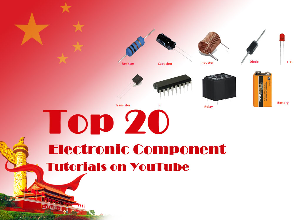
For workers who are just getting started in the electronic components industry, it is necessary to learn the knowledge of electronic components. Here E-components.globalbestshopping.com Electronic Components Network provides professional technical knowledge.
Below is a summary of the top 20 electronic component tutorials from YouTube. As long as you read these tutorials, you will basically be able to know the symbols and functions of various electronic components.
Top 20 electronic component tutorials on YouTube
All electronic components names and their symbols | Basic electronic components with symbols
This is the author of a YouTube channel who shares electronic circuit knowledge, electronic component symbols, and the use of home circuit equipment.
He shared “All electronic component names and their symbols, video explanation of basic electronic components with symbols”. The details include capacitor types, resistor types, shunt resistors, ferrite inductors, air-core inductors, laminations Iron core inductor.
sure! BEEE Works is an exciting YouTube channel dedicated to showcasing the wonderful world of technology, engineering and innovation to its viewers. Whether you are interested in robots, electronic equipment or future technology, BEEE Works can bring you unlimited surprises and fun.
On the BEEE Works channel you can discover all kinds of amazing projects and experiments. They experiment with making robots, electronic devices, and other innovative devices and document the process to share with everyone. Whether you are a technology enthusiast, a student or just curious about new things, BEEE Works can provide you with interesting video content.
In addition, BEEE Works has produced a series of tutorial videos to help beginners understand electronic technology and programming. Whether you want to learn Arduino, Raspberry Pi, or other electronics technology, they provide easy-to-understand explanations and practical guidance.
All in all, BEEE Works is a creative and passionate YouTube channel that brings viewers exciting content from the world of technology. Come join the BEEE Works community and explore the future of technology with them!
All Electronic Components Names and Pictures Part 1
Electronic components are an important part of electronic equipment and systems. They are used to implement different functions in circuits.
The video above talks about a lot of electronic component products. Let’s take a look at some common electronic components:
- Resistors: used to limit the flow of current and play the role of voltage divider and current shunt in the circuit.
- Capacitor: used to store charges and play a role in filtering, coupling, and DC blocking in the circuit.
- Inductor: used to store magnetic field energy and play a role in filtering, oscillation, delay, etc. in the circuit.
- Diode: It has unidirectional conductivity and can be used in circuits such as rectification, detection, and voltage stabilization.
- Transistor: It has the functions of amplification and switching, and can be used in amplification circuits, switching circuits, etc.
- Field effect tubes: including MOS tubes, etc., which have the advantages of high input impedance and low noise, and can be used in amplifier circuits, switching circuits, etc.
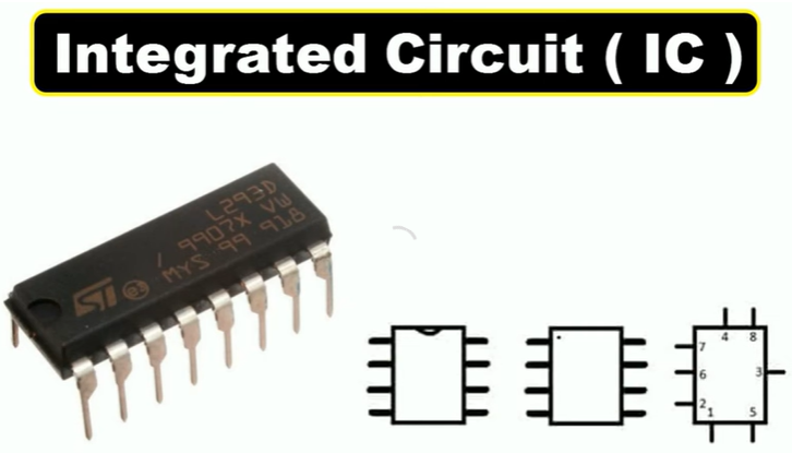
- Integrated circuit: Integrate multiple electronic components on one chip to realize complex circuit functions, such as operational amplifiers, microprocessors, etc.
- Sensor: Convert non-electrical quantities into electrical quantities, such as temperature sensors, pressure sensors, etc.
- Switching components: such as relays, switching tubes, etc., used to control the on and off of the circuit.
- Connectors: such as plugs, sockets, etc., used to connect different parts of the circuit.
The above are only some of the electronic components. In fact, there are many types of electronic components, and different components can be selected according to different circuit requirements.
10 Basic Electronics Components and their functions
Basics Electronic Components with Symbols and Uses
Description: In this Video I tell You 10 Basic Electronic Component Name Symbol And for what purpose we use that component watch the video to learn more about it.
Circuit symbols
Learn all the circuit symbols you need for your exams, and strategies to remember them. LESSON LINKS: SP10a Electric circuits – Pearson textbook (Edexcel exam board) P4.2 Current and charge – Oxford 3rd edition (AQA exam board) Physics explained in an easy to understand way to help you pass your physics exams, or just satisfy your curiosity about science.
Arduino Course for Everybody
Master the Arduino, a versatile electronics platform, through this comprehensive video course for beginners. Learn the fundamentals, build hands-on projects, explore advanced concepts, and harness the power of input devices to create your own electronic creations.
Basic Electronics For Beginners
This video provides an introduction into basic electronics for beginners. It covers topics such as series and parallel circuits, ohm’s law, light emitting diodes, resistors, potentiometers, voltage divider circuits and more.
The main content of the video tutorial includes technical knowledge such as Resistors, Series vs Parallel, Light Bulbs, Potentiometer, Brightness Control, Voltage Divider Network, Solar Cells, etc.
Basic Electronics for Beginners in 15 Steps
Video learning address: https://www.youtube.com/watch?v=a9VxTE3-bbA
In this video I will explain basic electronics for beginners in 15 steps. Getting started with basic electronics is easier than you might think. This video will hopefully demystify the basics of electronics so that anyone with an interest in building circuits can hit the ground running.
This is a quick overview into practical electronics and it is not my goal to delve deeply into the science of electrical engineering. If you are interested in learning more about the science of basic electronics, this channel is a good place to start your search. By the end of this video, anyone with an interest to learn basic electronics should be able to read a schematic and build a circuit using standard electronic components.
Basic Electronics for Beginners in 15 Steps
00:41 Step 1: Electricity
01:52 Step 2: Circuits
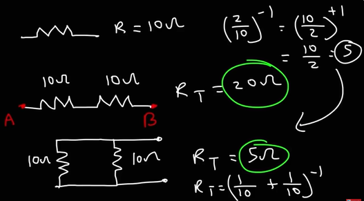
02:17 Step 3: Series and Parallel
02:47 Step 4: Resistors
04:14 Step 5: Capacitors
05:04 Step 6: Diodes
05:44 Step 7: Transistors
06:50 Step 8: Integrated Circuits
08:06 Step 9: Potentiometers
08:45 Step 10: LEDs
09:59 Step 11: Switches
10:19 Step 12: Batteries
11:03 Step 13: Breadboards
12:05 Step 14: Your First Circuit
12:38 Step 15: You’re on Your Own
How Resistors Work – Unravel the Mysteries of How Resistors Work
How resistors work is explained in the video “How Resistors Work – Unravel the Mysteries of How Resistors Work”! Explore the different types of resistors, how resistors work in circuits, and how to calculate resistance.
The video “How Resistors Work – Unravel the Mysteries of How Resistors Work” introduces in detail what a resistor is and its structure, potentiometers, fuse resistors, variable resistors, thermal resistors, temperature detectors, photoresistors, Strain gauges , Power dissipation, Parallel current divider and other knowledge.
There is a lot of knowledge about electronic components on The Engineering Mindset’s YouTube channel, including potentiometers, electrical engineering, basic electronics, what is a resistor, series resistors, cities and guilds, potentiometers, variable resistors, power electronics, Current limiting, carbon films, carbon composites, metal films, potentiometers, thermistors, RTDs, LDRs, light dependent resistors, SMDs, varistors and more.
What is a resistor?
A resistor is an electronic component used to limit the flow of electrical current. It works by impeding the flow of electrons, thereby dividing voltage and current in a circuit. The resistance value of a resistor is usually determined by its length, cross-sectional area, and material. In electronic circuits, resistors are essential components used to regulate signal levels, terminate transmission lines, reduce current flow, and provide stable voltage to other components. The resistance of a resistor is generally measured in ohms (Ω) and can be used in different circuits depending on its nominal value. Resistors are ubiquitous in electronic equipment, ranging from household appliances to industrial control circuits.
Resistor Structure
The resistor consists of three parts: resistor body, skeleton and terminal. It is only the resistor body that determines the resistance value. For a resistor body with uniform cross-section, the resistance value is:
R=ρL/A
Among them, ρ is the resistivity of the resistive material (ohm·cm), L is the length of the resistor body (cm), and A is the cross-sectional area of the resistor body (square centimeters).
The thickness d of the thin film resistor is very small and difficult to measure accurately, and ρ changes with the thickness. Therefore, ρ is regarded as a constant related to the thin film material, which is called film resistance. In fact, it is the resistance value of the square film, so it is also called square resistance (ohm/square). For a uniform film, its resistance is:
R=ρ/d
Among them, ρ is the resistivity of the resistive material (ohm·cm), and d is the thickness of the film (cm).
It is recommended to consult a book about resistors or consult a professional for more accurate information.
How do resistors work?
The working principle of a resistor is to control the intensity of the current in the circuit by using the resistance material’s blocking effect on the current. When current passes through a resistor, the electrical energy is converted into heat and dissipated, thereby limiting the current. The resistance value of a resistor is determined by its length, cross-sectional area and material, and different resistance values can be used to regulate the voltage and current in a circuit. In electronic circuits, resistors can be used for many purposes such as voltage dividing, current shunting, current limiting, and adjusting signal levels. They are one of the essential components in electronic equipment. Resistors are usually marked with a nominal resistance value and allowable deviation, which can be selected and applied according to the circuit needs.
The above video talks about a lot of electronic components. Here I will briefly introduce resistors to you. For research and analysis on resistors and other electronic components, please watch the above video tutorial.
Diodes Explained – The basics how diodes work working principle pn junction
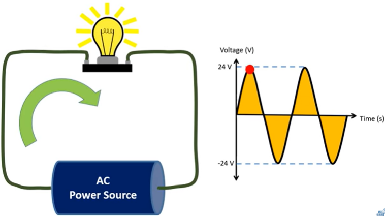
In this video we explain what a diode is, in this tutorial we will learn how diodes work, where diodes are used, why diodes are used and the different types. We study the diodes in half-bridge and full-bridge rectifiers to convert alternating current to direct current.
Video highlights include what a diode is, how it works, why diodes are used, and how to test diodes.
What is a diode?
A diode is an electronic device with two electrodes, an anode and a cathode. It is made of semiconductor materials such as silicon, selenium, germanium, etc. The diode has unidirectional conductivity. When a forward voltage is applied between the two poles of the diode, the diode conducts; when a reverse voltage is applied, the diode turns off. The turn-on and turn-off of the diode is equivalent to the turn-on and turn-off of the switch. In electronic circuits, diodes and resistors, capacitors, inductors and other components are used to make reasonable connections to form circuits with different functions to achieve AC rectification, modulation signal detection, limiting and clamping, and power supply voltage stabilization. and many other functions. Traces of diodes can be found whether in common radio circuits or in other household appliances or industrial control circuits.
How do diodes work?
The working principle of a diode is: when a forward voltage is applied to the diode, the diode conducts and current can flow through it; when a reverse voltage is applied to the diode, the diode cuts off and current cannot flow through it. This is due to the internal structure of the diode. There is a PN junction inside. When a forward voltage is applied, the forward conduction resistance of the PN junction is very small, while the reverse voltage enhances the reverse blocking capability of the PN junction. , making it impossible for current to pass. Therefore, the diode has unidirectional conductivity and its working principle is similar to that of a switch. It can achieve on and off states by controlling the voltage. In practical applications, diodes can be used together with other electronic components to form circuits with various functions to achieve various functions such as AC rectification, detection, limiting and clamping, and stabilization of power supply voltage.
Why use diodes?
The main reasons for using diodes are as follows:
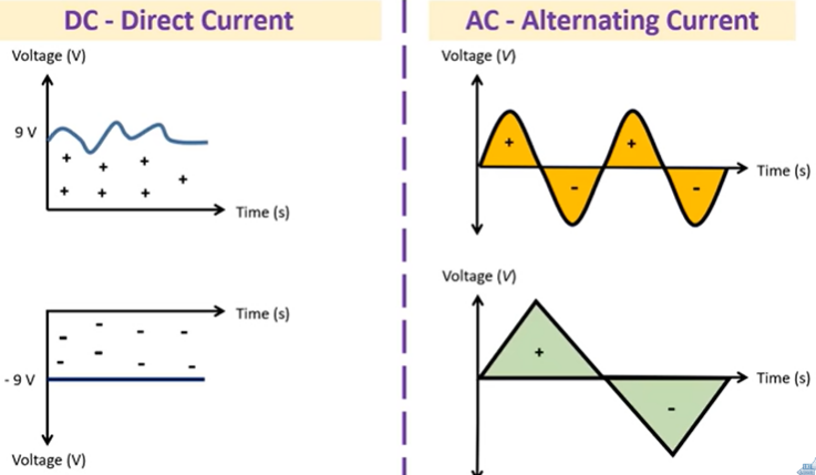
- Rectification: Using the unidirectional conductivity of diodes, alternating current in alternating directions can be converted into pulsating direct current in one direction. This is the most basic use of diodes.
- Switching element: Under the action of the forward voltage, the resistance of the diode is very small and it is in the on state, which is equivalent to an on switch; under the action of the reverse voltage, the resistance is very large and it is in the cut off state, like an off switch. switch. Using the switching characteristics of diodes, various logic circuits can be formed.
- Limiting component: After the diode is forward-conducted, its forward voltage drop remains basically unchanged. Utilizing this characteristic, it can be used as an amplitude limiting element in the circuit to limit the signal amplitude within a certain range.
- Relay diode: It plays a relay role in the inductance of the switching power supply and in inductive loads such as relays.
- Detection diode: plays a detection role in the radio.
- Varactor diode: used in the tuner of a TV.
- Fast switching speed: Because the PN junction of the diode can quickly switch from on to off state, it has fast switching speed. This allows the diode to be used in high-frequency and high-speed circuits to achieve fast signal processing.
- Low power consumption: Diodes have low power consumption due to their basic PN structure and no need for external power supply. This allows diodes to function in circuits with low voltage and low power consumption, such as mobile devices and battery-powered electronics.
- Packaging diversity: Diodes are available in various packaging forms to meet the installation requirements of different applications.
In summary, diodes have many unique properties and uses that make them occupy an important position in electronic engineering.
How to test a diode?
There are many ways to test diodes, the most common of which is the forward voltage drop measurement method. This method involves connecting a diode to a circuit and applying a forward voltage. The forward voltage drop of the diode is determined by measuring the voltage drop across it. The specific steps are as follows:
- Prepare tools: You need to prepare a digital multimeter to measure the voltage drop.
- Connect the diode: Connect the diode to the circuit, making sure the positive terminal is connected to the positive power supply and the negative terminal is connected to the negative power supply.
- Measure the voltage drop: Adjust the voltage measurement range of the digital multimeter to the DC voltage range, and connect the test pens to the positive and negative poles of the diode respectively. Record the measured voltage value. This value is the forward voltage drop of the diode.
- Analyze the results: Based on the measurement results, determine whether the diode type and parameters meet the requirements. Generally speaking, the forward voltage drop of a diode is between 0.6V and 0.7V, and different types of diodes may have slightly different voltage drop values.
In addition to the forward voltage drop measurement method, there are other methods to test diodes, such as using a mechanical multimeter or digital multimeter to measure forward and reverse resistance, and using a regulated power supply and a megger to measure the regulated voltage value. When using these methods, it is necessary to correctly distinguish the positive and negative poles of the red and black test leads, and to correctly connect the test equipment and diodes.
When testing diodes, you need to pay attention to safety issues. First, make sure that the supply voltage does not exceed the maximum input voltage of the test equipment. Secondly, do not reverse the positive and negative poles during the test to avoid short circuit or damage to the test equipment or diodes. Finally, keep your hands and test equipment dry during the test to avoid electric shock or short circuiting the equipment.
Inductors Explained – The basics how inductors work working principle
Inductors Explained, in this tutorial we look at how inductors work, where inductors are used, why inductors are used, the different types. We take an in depth look at how the circuits perform with a parallel resistive and inductive load as well as their profile with an oscilloscope.
Understand how inductors work
The working principle of an inductor is based on the principle of electromagnetic induction, that is, when the magnetic field changes, an induced electromotive force is generated in the conductor. Specifically, when an AC current passes through an inductor, the magnetic field around it changes, creating an induced electromotive force inside the inductor. This induced electromotive force interacts with the original magnetic field to produce a reverse braking torque, which reduces the current in the inductor. Therefore, the inductor has the function of hindering the change of current and is a commonly used electronic component.
Furthermore, the impedance of an inductor is frequency dependent, with its impedance increasing as frequency increases. Therefore, inductors have good filtering and frequency selection effects in high-frequency circuits and can be used for signal screening and interference suppression. At the same time, inductors can also be used for energy storage and current control to improve the stability and reliability of the circuit.
In short, the working principle of an inductor is mainly based on the principle of electromagnetic induction. It controls the change of current through changes in the magnetic field, thereby realizing various applications in the circuit.
Where to use inductor? Inductor working environment
Inductors are widely used in various electronic devices and systems, including but not limited to the following aspects:
- Power circuit: used for energy storage, filtering and current control, such as switching power supply, charger and adapter, etc.
- Signal processing circuit: used for signal screening and interference suppression, such as audio processing, radio frequency processing and communication systems.
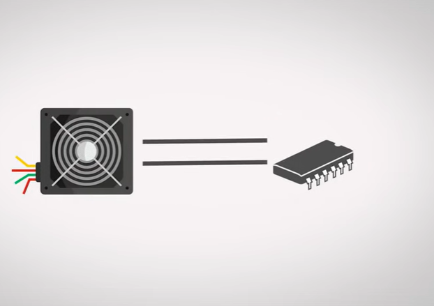
- Motor control circuit: used to control the start, stop and direction of motors, such as power tools, electric vehicles and robots.
- Lighting circuit: used to control current and protect lamps, such as LED lamps and fluorescent lamps.
- Sensor circuit: used to sense physical quantities such as magnetic field, temperature and pressure, such as Hall sensors, temperature sensors and pressure sensors.
The working environment of an inductor depends on its specific application and circuit requirements. Generally, factors such as voltage, current, frequency, temperature and humidity need to be taken into consideration. In some cases, inductors also need to withstand external conditions such as mechanical stress, vibration, and shock. Therefore, it is necessary to select the appropriate inductor model and specifications according to the specific working environment and circuit requirements.
Why use inductors?
The main reasons for using inductors are as follows:
- Energy storage: Inductors have an energy storage function and can convert electrical energy into magnetic energy and store it. When the current in the circuit changes, the inductor converts the change in current into a change in the magnetic field, thereby absorbing or releasing energy.
- Filtering: The combination of inductors and capacitors can form a filter, which can filter out signals at specific frequencies, thereby filtering and processing signals in the circuit.
- Current control: Inductors can control current. For example, in switching power supplies, inductors can control the amplitude and frequency of current to achieve the purpose of stabilizing the output voltage.
- Electromagnetic induction: Inductors can use the principle of electromagnetic induction to convert electrical energy into other forms of energy such as mechanical energy or thermal energy, thereby realizing the conversion and utilization of energy.
- Matching impedance: In some circuits, an inductor is required to match the impedance in the circuit to ensure the normal operation of the circuit.
In short, inductors have a variety of applications in circuits and can achieve functions such as energy storage, filtering, current control, electromagnetic induction, and impedance matching. Using inductors can improve the performance of circuits and increase the reliability and stability of equipment.
Different types of inductors
There are many different types of inductors, here are some of the common classifications:
Classification according to inductor shape
- Coil inductor: Coil inductor is the most common type of inductor, which is made of insulated copper wire or copper foil wound into a cylindrical or rectangular shape.
- Flat inductor: Flat inductor is a special type of inductor, which is made of multiple turns of thin copper foil stacked to save space.
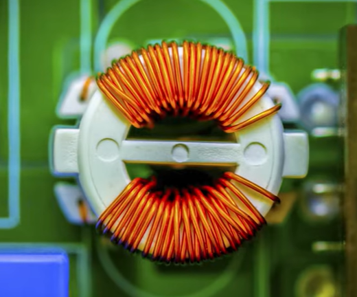
- Magnetic ring inductor: Magnetic ring inductor is an inductor with windings wrapped around a magnetic ring. It is usually used in high-frequency circuits.
Classification according to use
- Filter inductor: used as a filter in a circuit to remove noise or interference signals.
- Coupling inductor: used to couple two or more circuits together, usually used in amplification circuits.
- Induction inductor: used to sense current or voltage, usually used in sensors or current/voltage converters.
Classification according to core material
- Air-core inductor: An inductor without a magnetic core has a small inductance value and is mainly used in high-frequency circuits.
- Magnetic core inductor: An inductor with a magnetic core added to the wire has a large inductance value and is often used in low-frequency circuits.
- Iron core inductor: A magnetic core inductor made of iron as the main material. It has a large inductance value and is often used in low-frequency circuits.
Classification according to winding method
- Single-layer coil inductor: An inductor with only one layer of coil has a small inductance value.
- Multilayer coil inductor: An inductor composed of multiple layers of coils has a larger inductance value.
- Honeycomb coil inductor: An inductor with coils arranged like a honeycomb has a large inductance value.
Classification according to structure
- Fixed inductor: an inductor with a fixed structure and cannot be adjusted.
- Adjustable inductor: An inductor whose structure can be adjusted and its inductance value can be adjusted.
The above are different types of inductors. Different types have different characteristics and application scenarios. When using, the appropriate type should be selected according to actual needs.
An in-depth study of how circuits perform with parallel resistive and inductive loads
In circuits, parallel resistive and inductive loads can exhibit some interesting properties. Here are some basic concepts and principles about parallel resistive and inductive loads:
- Impedance of parallel resistors and inductors: In a parallel circuit, resistors and inductors have different impedance characteristics. The impedance of a resistor is real and independent of frequency, whereas the impedance of an inductor is complex and increases with frequency. Therefore, the total impedance of a parallel resistive and inductive load depends on their impedance value and phase angle.
- Distribution of current: Since parallel resistors and inductors have different impedance characteristics, the current is distributed between them. At low frequencies, the current in the resistor is larger, and at high frequencies, the current in the inductor is larger. This phenomenon of current distribution is called the “skin effect.”
- Phase relationship: In a parallel circuit, there is a phase relationship between the voltage and current of the resistor and inductor. At low frequencies, the voltage and current across the resistor are in phase, while at high frequencies, the voltage and current across the inductor are 90 degrees out of phase. Therefore, the total voltage and current phase of a parallel resistive and inductive load also depends on frequency.
- Energy storage: Inductive loads can store magnetic field energy, while resistive loads convert the energy into heat and dissipate it into the environment. In a parallel circuit, energy will be exchanged between the resistor and the inductor, forming a dynamic equilibrium state.
- Stability: The stability of parallel resistive and inductive loads depends on the parameters of the circuit and external conditions. Under certain circumstances, circuits may oscillate or become unstable. In order to obtain stable circuit performance, appropriate component parameters and circuit topology need to be selected.
In summary, circuits with parallel resistive and inductive loads have many interesting properties and behaviors. Through in-depth study and understanding of these characteristics, a deeper understanding and application of circuit design, optimization and control can be achieved.
Use an oscilloscope to view their outlines
Using an oscilloscope to view the outline of a resistor can provide detailed information about its shape, size, and quality. By observing the outline of a resistor, it is possible to evaluate its manufacturing quality, determine its size and calculate its effective resistance value. Additionally, an oscilloscope can be used to detect defects and irregularities on resistors such as opens, shorts, corrosion, and uneven wire distribution. This is critical to ensure the reliability and performance of the resistor. It is important to note that using an oscilloscope to view the profile of a resistor requires certain skills and experience, as there may be errors and uncertainties in the measurement process. Therefore, appropriate precautions should be taken when taking measurements and ensure that appropriate instruments and measurement methods are used.
Tutorial Guide to Inductors and Inductance
This video tutorial details how inductors and inductors work and their role in a circuit. How inductors behave in a circuit, and how inductors can generate extremely high voltages by opposing changes to the flow of current.
How Does a MOSFET Work?
This video completely explains the structure, channel formation, current flow, characteristics, pinch-off effect, and circuit symbols of Metal Oxide Semiconductor Field Effect Transistor.
What is a MOSFET?
MOSFET, the full name of metal oxide semiconductor field effect transistor, is a commonly used semiconductor device. It uses the electric field effect of the control input loop to control the output loop current. It has the advantages of high input resistance, low noise, low power consumption, large dynamic range, easy integration, no secondary breakdown phenomenon, and wide safe working area. It has become A strong competitor for bipolar transistors and power transistors.
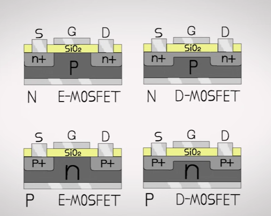
MOSFET can be divided into two types: N-channel and P-channel according to different conductive channels. N-channel MOSFETs are often called NMOS, while P-channel MOSFETs are called PMOS.
The basic structure of MOSFET includes three terminals: source, gate and drain. The source and drain are usually made of N-type or P-type semiconductor materials. When a forward voltage is applied between the gate and source, the MOSFET turns on and current can flow through the channel between the source and drain.
In addition, the power MOSFET is a special kind of MOSFET, and its types include P-channel and N-channel. Power MOSFET has low on-resistance and is suitable for high-current and high-voltage application scenarios, such as motor control, power switches, etc.
In summary, MOSFET is an important semiconductor device that is widely used in various electronic devices and systems.
How Does a MOSFET Work?
This video completely explains the structure, channel formation, current flow, characteristics, pinch-off effect, and circuit symbols of Metal Oxide Semiconductor Field Effect Transistor.
The key points of the tutorial on MOSFET semiconductor devices include Basics of current flow, Semiconductor and its doping, PN Junction and it’s biasing, Structure of MOSFET, Working: Cut-Off Region, Working: Channel Formation, For future people, Working: Ohmic Region, Working: Pinch-Off, Working: Saturation Region, MOSFET characteristics, Another MOSFET and MOSFET circuit symbol.
Entire step-by-step PCB design process going through the schematic, layout, and routing of a ‘barebones’ STM32F4-based PCB including USB, a sensor, GPIO header, and small power supply circuitry in Altium Designer. All the way from schematic creation, through to four-layer PCB layout and routing, as well as sending it off for manufacture and assembly via E-components.globalbestshopping.com .
Electronics & Physics Learning in 5 Simple Projects (with ELEGOO Upgraded Electronics Fun Kit)
This video includes 5 simple projects that don’t require an Arduino control board but still can practically implement some daily-life functions. Users can now start the journey of electronics & physics learning in the most direct and convenient way.
Laptop motherboard components testing using The multimeter – laptop motherboard repair
What is a capacitor – Electronics Tutorial For Beginners
What is a capacitor – Electronics Tutorial For Beginners
Do you know what is a capacitor?
Most people don’t. A capacitor is an important electronic component that stores energy in an electric field. It’s used in everything from televisions to cars. Without capacitors, our world would be a very different place. In this video, we’re going to take a closer look at what is a capacitor and learn why they are so important.
00:00 What is a capacitor
00:31 History of Capacitor
00:57 How does a capacitor work
1:21 What is a capacitor used for
1:49 Why do we need capacitors
2:22 Capacitors types
4:00 What is the symbol and unit of the capacitor
4:21 How to measure capacitor with a multimeter
4:43 What is a typical sign that a capacitor is bad or has failed
Capacitors, Resistors, and Electronic Components
What do all those capacitors, resistors, chokes, and transistors on your motherboard actually do?
The main content of this video includes Capacitors, Chokes, Transistors, MOSFETs, Squarespace, etc.
Essential Electronics Components that you will need for creating projects
The electronic components used in this electronic project include Storage Box, Resistor Kit E24 1/4W, 10k Resistor, 1 Resistor Shunt, 1206 Resistor Book Kit, Electrolytic Capacitor Kit, Ceramic Capacitor Kit, 1206 SMD Capacitor Kit, Power Inductor Kit, LM7805 , LM7812, Boost Converter MT3608, Buck Converter LM2596, MCP602, LM358 OpAmp, IRF5305, IRLZ44N, TC4420, TC4428, IR2113, BC547, BC557, NE555, Diode Kit, TLC555, HCF4013BE, 74HC14, LED 5mm Set, Ar duino Nano, Trimmer, Potentiometer, Fuse Holder, Fuse Kit, Tactile Push Button, Toggle Switch, Screw Terminal, IC Sockets, Male Female Header, Breadboard, Jumper Wires, Alligator Clip Wires, Resistor, Capacitor, Inductor, OpAmp, MOSFET, BJT, Diode, 555 Timer , D-type Flip Flop, Schmitt Trigger.
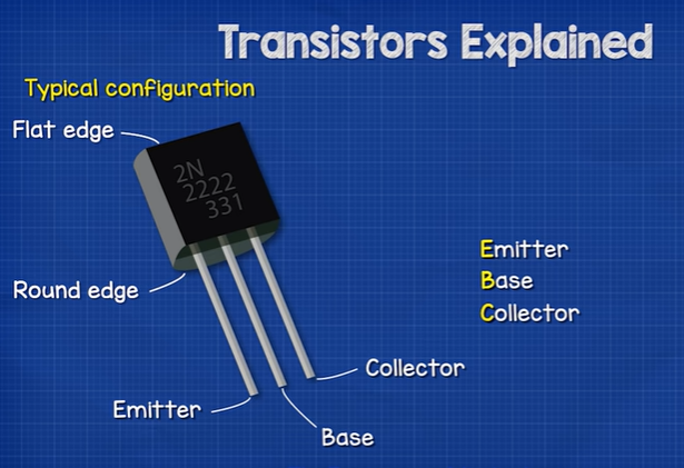
Transistors Explained – How transistors work
Transistors how do transistors work. In this video we learn how transistors work, the different types of transistors, electronic circuit basics, how to build a transistor circuit, transistor amplifier, current gain beta, npn, pnp, heat sink, electronics and electrical engineering. Plus more!
Transistors – NPN & PNP – Basic Introduction
This electronics video tutorial provides a basic introduction into NPN and PNP transistors which are known as BJTs or Bipolar Junction Transistors.
This video discusses the 3 operating regions of a transistor – the cutoff, active, and saturation region. It also explains how the transistors act as switches and how to determine the current and voltages in a transistor base bias circuit.
An oscilloscope can be used to observe some characteristics of an inductor, but it is not the best measuring instrument. An oscilloscope can be used to observe the voltage and current waveforms in an inductor to analyze its working status and performance. However, the frequency range and sensitivity of an oscilloscope may be limited and may not be accurate enough for some high-precision and high-frequency measurements.
To measure the parameters and performance of an inductor more accurately, you need to use professional inductance measuring instruments, such as inductance meters, LCR measuring instruments, etc. These instruments provide more accurate measurements with higher measurement accuracy and a wider frequency range. Therefore, in the measurement and analysis of inductors, professional measuring instruments should be selected to obtain more accurate and reliable results.