Component aging test methods and standards

Component aging test methods and standards

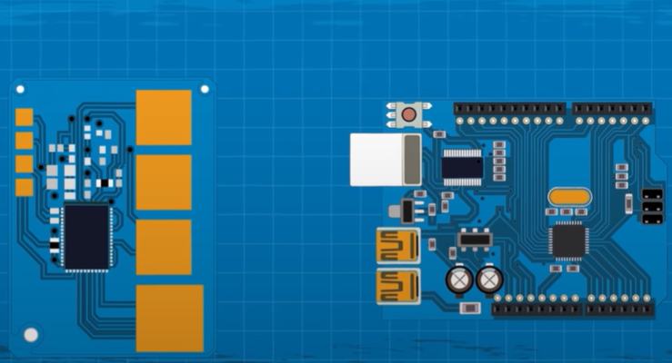
Component aging test methods and standards are important means to evaluate the reliability of components.

They are designed to test the performance of components in harsh environments by simulating various stress factors under actual working conditions.

Standards vary by product and application, and test time, conditions, and methods need to be strictly controlled to avoid damage to components.

Methods to evaluate the aging effect include visual inspection, performance testing and life testing.

The purpose of component aging test

Component aging test is a method to evaluate the performance stability and reliability of components under specified conditions.

Through aging tests, potential early failures or performance degradation problems can be discovered and eliminated, ensuring that components can operate reliably under normal working conditions.

The purpose of component aging test

Classification of aging tests

  1. Natural aging: During the product life cycle, let the components run naturally for a period of time in the actual working environment to observe their performance changes and failure modes. This method is often used to evaluate the long-term reliability of components.
  2. Accelerated aging: Accelerate the aging process of components by applying stress that exceeds normal working conditions. Commonly used accelerated aging conditions include high temperature, high humidity, high voltage, high current, etc. Accelerated aging is often used to shorten evaluation cycles and quickly identify potential problems.

Aging test method

  1. Constant stress method: Under certain stress conditions, a batch of components are aged for a long time to observe their failure time. This method is suitable for situations where it is known that stress has a greater impact on components.
  2. Step stress method: Gradually increase the stress until the component fails, and record the failure time at each stress level. This approach provides a more complete understanding of component performance under different stress conditions.
  3. Sequential stress method: Aging is performed at multiple different stress levels, each stress level is maintained for a certain period of time, and then transferred to the next stress level. This method can simultaneously examine the effects of multiple stress factors on components.
What is an Overload Relay? Connection & Working Principle

Standards for aging tests

  1. Environmental conditions: According to the characteristics and application scenarios of the components, select appropriate environmental conditions such as temperature, humidity, air pressure, etc. for aging.
  2. Test samples: Select a certain number of components as test samples, and determine the number of samples according to the test purpose and test cycle.
  3. Failure criteria: Clarify the failure criteria of components, such as performance degradation, parameter drift, open circuit, short circuit, etc.
  4. Data analysis: Perform statistical analysis on test data, calculate the life distribution, failure rate and other indicators of components, and evaluate their reliability.
  5. Report writing: Write a test report according to the prescribed format, including test purpose, sample information, test conditions, data analysis, conclusions, etc.

Analysis of common failure modes

During component aging testing, common failure modes include:

  1. Performance degradation: The performance parameters of components gradually deviate from the normal range, which may lead to abnormal circuit function.
  2. Fatigue failure: Due to the repeated action of mechanical stress or electrical stress, the internal structure of the component undergoes fatigue damage, eventually leading to fracture or fatigue failure.
  3. Electromigration: Under the action of electric current, metal ions migrate in semiconductor materials, causing circuit performance degradation.
  4. Thermal failure: component performance degradation or failure caused by overheating.
  5. Environmental stress corrosion: Under specific environmental conditions (such as moisture, salt spray, etc.), components are corroded and fail.

For these failure modes, corresponding measures can be taken to simulate and evaluate during the aging test so that problems can be discovered and solved in a timely manner.

The significance of aging test

Through the component aging test, the following significance can be obtained:

  1. Improve product quality: Screen out early failure components through aging tests, reduce the failure rate of products in use, and improve overall product quality.
  2. Shorten the product development cycle: By accelerating the aging of components, potential problems can be discovered and solved as early as possible, thus shortening the product development cycle.
  3. Reduce maintenance costs: By conducting aging tests on components, potential problems can be discovered before the product is put into use, thus avoiding the costs of later maintenance and replacement.
  4. Improve production efficiency: Through batch aging tests, qualified components can be quickly screened out on the production line to improve production efficiency.
  5. Ensure product reliability: Through strict aging tests on components, we ensure that products can operate stably and reliably under various working conditions and improve customer satisfaction.

The above content is for reference only. If you need more detailed information, please refer to the international standards or industry specifications related to component aging tests.

Frequently Asked Questions

What is component aging test?

The component aging test is a reliability test that aims to check whether the components can work normally under various harsh conditions by simulating the stress conditions that the components may encounter in actual work.

What is the purpose of the aging test?

The purpose of the aging test is to detect the reliability of components, improve product stability and reliability, and reduce the risk of product failure caused by component failure.

What are the methods for aging tests?

Aging test methods include high-temperature aging, low-temperature aging, humidity aging, vibration aging, impact aging, etc.

What are the standards for aging testing?

The standards for aging tests are usually formulated based on different product standards and industry standards. For example, MIL-STD-2000 is the reliability test standard for U.S. military electronic equipment, and GJB150 is the environmental test method standard for my country’s military equipment.

How long does the aging test take?

The timing of the aging test varies with different products and applications and needs to be determined according to specific standards and requirements. Generally speaking, the longer the aging test, the more stringent the reliability testing of components.

What impact does aging testing have on components?

The aging test will produce certain stress effects on components, such as high temperature, low temperature, humidity, vibration, impact, etc. These stresses may cause changes in the physical and chemical properties of components, affecting their performance and reliability. Therefore, the test conditions and time need to be strictly controlled during the aging test to ensure that no excessive damage is caused to the components.

How to evaluate the aging effect of components?

Evaluating the aging effect of components can be achieved through a variety of methods, such as appearance inspection, performance testing, life testing, etc. These methods can help us understand the performance of components in aging tests to determine their reliability and stability.

Potentiometer purchasing catalog and price analysis

Potentiometer purchasing catalog and price analysis

Potentiometer procurement catalog and price analysis are important links to ensure the purchase of cost-effective potentiometers.

It is necessary to pay attention to specifications, types, price ranges, supplier selection and quality assurance to reduce procurement costs and ensure product quality.

Introduction

A potentiometer is a commonly used electronic component, mainly used to adjust the voltage or current in a circuit. With the development of science and technology, the application fields of potentiometers are becoming more and more extensive, including home appliances, communications, automotive electronics, industrial control and other fields.

Therefore, it is very important for purchasers to understand the purchase catalog and price analysis of potentiometers. This article will conduct a detailed analysis of the potentiometer purchase catalog and price.

Potentiometer Types and Specifications

There are many types and specifications of potentiometers. Common types include rotary potentiometers, straight sliding potentiometers, patch potentiometers, etc. In terms of specifications, the resistance range, accuracy, power and other parameters of the potentiometer have a great impact on the price and use effect. Purchasing personnel need to choose the appropriate type and specification based on actual needs.

Potentiometer purchasing catalog

Supplier selection

When purchasing potentiometers, it is very important to choose a supplier with a good reputation and reliable quality. It is recommended that purchasing personnel investigate and compare suppliers on the market and select competitive suppliers.

Product certification

For certain industries, such as automotive electronics and medical equipment, the purchased potentiometers need to comply with relevant standards and certifications. Therefore, you need to pay attention to the certification status of the product when purchasing.

Delivery time and inventory

When choosing a supplier, you need to pay attention to its delivery time and inventory availability. Long lead times or insufficient inventory can cause production to suffer.

After-sales service

Good after-sales service can ensure the long-term stable operation of the potentiometer and reduce maintenance costs. Therefore, when choosing a supplier, you need to pay attention to the quality and coverage of its after-sales service.

Potentiometer Price Analysis

Cost composition

The cost of a potentiometer is mainly composed of material costs, manufacturing costs, R&D costs, sales and management expenses, etc. Among them, material cost and manufacturing cost are the most important costs.

Factors affecting price

(1) Market size: The size of the market directly affects the supply and demand of potentiometers, thereby affecting the price.
(2) Industry competition: The number and strength of competitors in the industry will affect prices. If there are many competitors and fierce price competition, the price may be lowered.
(3) Technical level: The price of potentiometers with higher technical level is relatively higher. This is because high-tech products require more R&D and manufacturing costs.
(4) Quality assurance: Quality assurance is an important factor in the price of potentiometers. High-quality potentiometers require a more stringent production process and a more complete quality inspection system, so the price is relatively high.
(5) Supply and demand: When the market supply exceeds demand, the price may decrease; when the market supply exceeds demand, the price may increase.
(6) International economic situation: Changes in the international economic situation will affect cost factors such as exchange rates and tariffs, thereby affecting the price of potentiometers.
(7) Policies and regulations: Changes in policies and regulations will affect industry development and market competition, thereby affecting the price of potentiometers.

Price fluctuation trend

With the continuous advancement of technology and changing market demand, the price of potentiometers shows a certain fluctuation trend. Generally speaking, when new technologies and new products are launched, the price is relatively high; as the technology becomes more popular and market competition intensifies, the price will gradually decrease. At the same time, high-quality potentiometers are relatively expensive due to their high technical content and high quality assurance.

Summary and suggestions

  1. Purchasing personnel need to understand market conditions and supplier situations, and select appropriate suppliers and products based on actual needs. At the same time, attention should be paid to product quality and after-sales service to reduce maintenance costs.
  2. In terms of price analysis, the impact of various factors on price must be comprehensively considered. We must not only focus on short-term price fluctuations and ignore long-term stability and quality assurance.
  3. For large manufacturers, they can consider establishing long-term cooperative relationships with suppliers to reduce costs and improve quality assurance through bulk purchasing and customized services.

Potentiometer Q&A

How to determine the size of a potentiometer?

When determining the specifications of the potentiometer, parameters such as resistance, accuracy, and power need to be considered. These parameters need to be selected based on actual circuit requirements. For example, for applications that require adjusting audio signals, you can choose a potentiometer with a resistance between 10-100kΩ.

How to choose the type of potentiometer?

There are many types of potentiometers, such as rotary type, straight sliding type, patch type, etc. Choosing the appropriate type requires consideration of the application scenario and circuit design. For example, for occasions where fine adjustment is required, you can choose a rotary potentiometer; for occasions where space is limited, you can choose a patch potentiometer.

How to determine the price range of a potentiometer?

The price of a potentiometer is affected by many factors, such as brand, quality, material, workmanship, etc. Generally speaking, the price of imported brand potentiometers is higher, while the price of domestic potentiometers is relatively low. At the same time, the price of high-quality potentiometers is relatively high. Therefore, when determining the price range of a potentiometer, you need to consider your actual needs and budget.

How to compare prices of potentiometers?

When comparing prices of potentiometers, factors such as price differences, quality assurance, and after-sales service of different suppliers need to be considered. At the same time, you also need to pay attention to the false quotations or low price traps of some suppliers. Therefore, a comprehensive evaluation is required when selecting a supplier.

How to avoid quality problems when purchasing potentiometers?

In order to avoid quality problems when purchasing potentiometers, it is recommended to choose brands and suppliers with quality assurance and conduct sample testing. At the same time, you need to pay attention to the packaging and labeling of the product when purchasing, and conduct appearance and performance inspections during acceptance. For products with quality problems, the supplier needs to be contacted in time for processing.

Electrolytic capacitor design and manufacturing specifications

Electrolytic capacitor design and manufacturing specifications

Electrolytic capacitor design and manufacturing specifications are key factors in ensuring product quality and reliability.

They involve dielectric material selection, plate design, sealing and housing requirements, pin and connection regulations, and temperature characteristics. Strict compliance with these specifications is necessary to manufacture high-performance electrolytic capacitors.

The capacitor is assembled on the PCB - Electrolytic capacitor design and manufacturing specifications

The design and manufacturing specifications of electrolytic capacitors is a complex and specialized field that encompasses knowledge from multiple disciplines, including electrical engineering, chemistry, physics, and materials science.

The following is a detailed introduction to electrolytic capacitor design and manufacturing specifications.

Design specifications

Dielectric material

Choosing the appropriate dielectric material is one of the key factors in the design of electrolytic capacitors. Commonly used dielectric materials include aluminum, tantalum, niobium, etc. According to different application requirements, select dielectric materials with appropriate dielectric constant, breakdown voltage and physical properties.

Capacitor manufacturers in China

Plate design

The plate is the core part of the electrolytic capacitor and consists of a positive plate and a negative plate. The positive plate usually uses metal foil, while the negative plate uses a corresponding dielectric material. The design of the plate should consider current capacity, voltage resistance, mechanical strength and stability requirements.

Sealing and housing

The sealing and housing design of electrolytic capacitors should have sufficient mechanical strength and airtightness to protect the internal capacitor components from the external environment. In addition, the shape and size of the enclosure should comply with relevant standards and specifications to ensure its correct installation and connection in the circuit.

capacitor design and manufacturing

Pins and connections

The pins and connections of the electrolytic capacitor should be designed to ensure reliable connection to the circuit board. The pin material selection should be compatible with the circuit board material to avoid corrosion and oxidation. At the same time, the length and diameter of the pins should meet the corresponding mechanical strength and electrical performance requirements.

Temperature characteristics

The temperature characteristics of electrolytic capacitors should also be considered during the design and manufacturing process. Temperature has a great impact on the performance and service life of electrolytic capacitors, so appropriate materials and processes should be selected to maintain stable performance under various temperature conditions.

Manufacturing Specifications

Preparation process

Before manufacturing electrolytic capacitors, a series of preparations are required. It includes cleaning, cutting, coating and other process steps to ensure that the surface of the capacitor components is clean and smooth, laying a good foundation for the subsequent manufacturing process.

Winding process

The winding process of electrolytic capacitors is the process of winding the positive plate, dielectric material and negative plate together in a certain order to form the capacitor element. The key to the winding process is to control the tension, speed and direction of the winding to ensure the density and consistency of the components.

Pin welding

Pin welding is the process of soldering the pins of an electrolytic capacitor to the corresponding terminals. Welding temperature, time and pressure should be controlled during welding to ensure welding quality and avoid false welding, false welding and other phenomena.

Assembly process

The assembly process of electrolytic capacitors is the process of installing the manufactured capacitor components into the corresponding shell and performing sealing treatment.

During the assembly process, care should be taken to protect the components from damage while ensuring the airtightness and aesthetics of the housing.

Aging and testing

Aging and testing are indispensable links in the manufacturing process and are used to check and evaluate the performance and stability of electrolytic capacitors.

The aging process usually includes high-temperature aging, low-temperature aging, humidity aging and other links to simulate the actual working conditions of the capacitor.

Testing includes electrical performance testing, mechanical performance testing and environmental adaptability testing to ensure that the product meets relevant standards and specifications.

Packaging and transportation

Packaging and transportation of electrolytic capacitors are also important aspects of manufacturing specifications. Packaging materials should be moisture-proof, shock-proof, and dust-proof to ensure that the product is not damaged during transportation. At the same time, the markings on the packaging should be clear and accurate to facilitate product traceability and management.

In general, the design and manufacturing specification of electrolytic capacitors is a complex and rigorous process that requires comprehensive consideration of multiple factors.

Quality and process parameters must be strictly controlled in every aspect from design to manufacturing to ensure that the performance and reliability of the final product meet expected standards and requirements.

At the same time, it is also very important to continuously improve and optimize the design and manufacturing process to further enhance the competitiveness of products.

Frequently Asked Questions

What are the dielectric materials of electrolytic capacitors?

Commonly used dielectric materials for electrolytic capacitors include aluminum, tantalum, niobium, etc. Depending on the application requirements, dielectric materials with appropriate dielectric constant, breakdown voltage, and physical properties can be selected.

What factors should be considered in plate design of electrolytic capacitors?

The plate design of electrolytic capacitors should consider current capacity, withstand voltage, mechanical strength and stability requirements. The positive plate usually uses metal foil, while the negative plate uses a corresponding dielectric material.

What characteristics should the sealing and housing design of electrolytic capacitors have?

The seal and housing design of electrolytic capacitors should have sufficient mechanical strength and airtightness to protect the internal capacitor components from the external environment. The shape and size of the enclosure should comply with relevant standards and specifications to ensure its correct installation and connection in the circuit.

What issues should be paid attention to in the pin and connection design of electrolytic capacitors?

The pins and connections of the electrolytic capacitor should be designed to ensure a reliable connection to the circuit board. The pin material selection should be compatible with the circuit board material to avoid corrosion and oxidation. At the same time, the length and diameter of the pins should meet the corresponding mechanical strength and electrical performance requirements.

How should the temperature characteristics of electrolytic capacitors be considered?

The temperature characteristics of electrolytic capacitors should be considered during the design and manufacturing process. Temperature has a great impact on the performance and service life of electrolytic capacitors, so appropriate materials and processes should be selected to maintain stable performance under various temperature conditions.

What are the key points in the winding process of electrolytic capacitors?

The winding process of electrolytic capacitors is the process of winding the positive plate, dielectric material and negative plate together in a certain order to form the capacitor element. The key to the winding process is to control the tension, speed and direction of the winding to ensure the density and consistency of the components.

What issues should be paid attention to when welding the pins of electrolytic capacitors?

Pin soldering of electrolytic capacitors is the process of soldering the pins to the corresponding terminals. Welding temperature, time and pressure should be controlled during welding to ensure welding quality and avoid false welding, false welding and other phenomena.

Vacuum circuit breaker switching capacitor current aging test

Vacuum circuit breaker switching capacitor current aging test

The vacuum circuit breaker switching capacitor current aging test is an important test for the performance of the vacuum circuit breaker.

Vacuum circuit breakers are widely used in power systems, mainly for control and protection circuits. In the switching capacitor current aging test, the vacuum circuit breaker needs to undergo multiple opening and closing operations to test the stability and reliability of its performance.

Test purposes

The purpose of the switching capacitor current aging test is to test the performance of the vacuum circuit breaker under multiple switching operations, especially the performance when switching capacitor current.

Vacuum circuit breaker switching capacitor current aging test

Through this test, changes in the mechanical, electrical and thermal properties of the circuit breaker after multiple operations can be discovered and evaluated to ensure its stability and reliability during long-term use.

Test principle

The capacitor current aging test is based on the basic principles of capacitors. In power systems, capacitors are common reactive power compensation devices used to improve the power factor of the system, reduce line losses and improve the voltage quality of the power grid. When a vacuum circuit breaker switches capacitor current, it needs to withstand higher current and voltage. Through multiple opening and closing operations, the performance of the vacuum circuit breaker under high current and high voltage can be tested.

Experiment procedure

Experiment procedure

  1. Preparation stage: Select a suitable vacuum circuit breaker, install and wire it according to regulations. Prepare appropriate power supplies, measuring instruments and auxiliary equipment.
  2. Initial testing: Before starting the test, perform an initial testing on the mechanical, electrical and thermal properties of the vacuum circuit breaker to establish reference data.
  3. Set conditions: Set power parameters, including voltage, current and frequency, to meet the charging and discharging needs of the capacitor. Set the operating conditions of the vacuum circuit breaker, such as the number of operations, interval time, etc.
  4. Test operation: Carry out multiple opening and closing operations according to the set conditions, and monitor various performance parameters of the vacuum circuit breaker in real time.
  5. Data recording: Record in detail the performance parameters after each operation, such as mechanical characteristics, electrical characteristics and thermal characteristics, etc.
  6. Result analysis: Compare the initial detection data with the data after the test, and analyze the performance changes of the vacuum circuit breaker after multiple opening and closing operations.
  7. Evaluation and reporting: Based on the analysis results, evaluate the performance level of the vacuum circuit breaker and write a detailed test report.

Precautions

  1. Safety first: Since the capacitor current may be very high, appropriate safety measures should be taken during testing, such as wearing protective clothing, using insulated tools, etc.
  2. Accuracy requirements: During the test process, high-precision measuring instruments should be used to ensure the accuracy and reliability of the data.
  3. Comply with regulations: When conducting tests, relevant national and industry standards should be observed to ensure test compliance.
  4. Preventive measures: During the test, pay close attention to the status changes of the vacuum circuit breaker, and handle any abnormalities in time.
  5. Complete records: All data and phenomena during the test should be recorded in detail for subsequent analysis and evaluation.
  6. Environmental protection: After the test, the waste generated should be disposed of in accordance with relevant regulations to ensure that the impact on the environment is minimized.
  7. Personnel training: Personnel conducting the test should receive professional training, be familiar with relevant equipment and operating procedures, and have necessary safety awareness and skills.
  8. Equipment maintenance: Regularly maintain and maintain the test equipment to ensure its normal operation and service life.
  9. Summary and improvement: Based on the test results and evaluation reports, summarize experience and lessons, put forward improvement measures and suggestions, and continuously improve the performance and quality of vacuum circuit breakers.

In short, the vacuum circuit breaker switching capacitor current aging test is an important test task and is of great significance to ensure the reliability and stability of the vacuum circuit breaker.

During the test process, relevant regulations and standards should be strictly followed to ensure the accuracy and reliability of the test results.

At the same time, strengthening personnel training and equipment maintenance are also important measures to ensure the smooth progress of the test.

Frequently asked questions and solutions

  1. Circuit breaker contacts worn: After multiple opening and closing operations, the circuit breaker contacts may become worn. This may lead to poor contact contact, increase contact resistance, and affect the performance of the circuit breaker. Solution: Check and replace the contacts regularly to ensure that the smoothness and material of the contact surface meet the requirements.
  2. Mechanical structure loose: After multiple operations, the mechanical structure of the circuit breaker may become loose, affecting the accuracy and reliability of its action. Solution: Regularly inspect and tighten mechanical components to ensure they are solid and reliable.
  3. Degradation of insulation performance: After switching on and off high voltages and large currents for many times, the insulation material of the circuit breaker may age, resulting in a decrease in insulation performance. Solution: Regularly check and replace insulation materials to ensure that their electrical performance meets requirements.
  4. Unstable thermal performance: After multiple operations, the thermal performance of the circuit breaker may change, affecting its normal operation. Solution: Strengthen the heat dissipation design, clean the heat dissipation channel regularly, and ensure that the circuit breaker works at normal temperature.
  5. Operating mechanism stuck: The operating mechanism may get stuck after multiple operations, affecting the normal operation of the circuit breaker. Solution: Lubricate the operating mechanism regularly to ensure flexible movement.

Future outlook

With the continuous advancement of science and technology and the increasing complexity of power systems, the performance requirements for vacuum circuit breakers are becoming higher and higher. In the future, switching capacitor current aging tests will pay more attention to the application of intelligent and automated technologies.

By introducing advanced sensors and detection equipment, real-time monitoring and automatic control of the test process can be achieved, improving the accuracy and reliability of the test. At the same time, with the development of big data and cloud computing technology, the processing and analysis of test data will be more in-depth and comprehensive, helping to better evaluate the performance of vacuum circuit breakers and discover potential problems.

In summary, the vacuum circuit breaker switching capacitor current aging test is an important means to ensure the performance of the vacuum circuit breaker.

By strictly abiding by test regulations and standards, strengthening personnel training and equipment maintenance, the accuracy and reliability of the test can be ensured.

At the same time, taking corresponding solutions to common problems in the test can further improve the performance and quality of the vacuum circuit breaker. In the future, with the introduction of intelligent and automated technologies, the switching capacitor current aging test will be more efficient and accurate, providing a strong guarantee for the stable operation of the power system.

FAQs

What is the vacuum circuit breaker switching capacitor current aging test?

The burn-in test is a method of simulating the actual operating operation of a vacuum circuit breaker, especially when switching capacitor currents. In this way, the performance and reliability of vacuum circuit breakers can be tested and evaluated.

Why is it necessary to conduct vacuum circuit breaker switching capacitor current aging test?

In practical applications, vacuum circuit breakers may undergo frequent switching operations, especially when switching capacitive currents. In order to ensure the stability and reliability of the vacuum circuit breaker, aging tests are required to simulate actual operating conditions and test its performance.

What are the common problems in the vacuum circuit breaker switching capacitor current aging test?

a. Unstable opening and closing operation: The vacuum circuit breaker may exhibit unstable operation when opening and closing the capacitor current. This may be due to problems in structural design or manufacturing process.
b. Contact ablation: When switching capacitor current, if the contact design of the vacuum circuit breaker is unreasonable or the material selection is inappropriate, contact ablation may occur.
c. Mechanical structure wear: Frequent opening and closing operations may cause wear and tear on the mechanical structure, thereby affecting the life and reliability of the vacuum circuit breaker.
d. Electromagnetic interference problem: When switching capacitor current, electromagnetic interference may be generated, affecting the normal operation of surrounding equipment.

How to solve common problems in the vacuum circuit breaker switching capacitor current aging test?

a. Optimize structural design: Optimize the structure of the vacuum circuit breaker, especially the design of the contacts and mechanical structure, to improve its stability and reliability.
b. Improve manufacturing process: Use advanced manufacturing processes and technologies to ensure that the manufacturing quality of vacuum circuit breakers meets requirements.
c. Enhance material selection: Select materials suitable for switching capacitor current to reduce the possibility of contact ablation.
d. Enhance anti-interference capability: Reduce the generation of electromagnetic interference by improving design and adopting appropriate filtering technology.

How to evaluate the results of vacuum circuit breaker switching capacitor current aging test?

The results of the aging test are evaluated according to actual needs and standards. The performance of a vacuum circuit breaker can be evaluated by comparing test data with expected results. In addition, the competitiveness of the vacuum circuit breaker can be evaluated by comparing its performance with other similar products.

How to improve the accuracy of the vacuum circuit breaker switching capacitor current aging test?

a. Use high-precision testing equipment: More accurate data can be obtained by using high-precision testing equipment.
b. Standardized operating procedures: Ensure the standardization and standardization of test operations to obtain consistent results.
c. Regular calibration of equipment: Calibrate test equipment regularly to ensure its accuracy.
d. Strengthen personnel training: Provide training to test personnel to improve their skills and accuracy.

What is the future development trend of vacuum circuit breaker switching capacitor current aging test?

With the continuous advancement of technology, the future development trends of vacuum circuit breaker switching capacitor current aging tests may include: more efficient testing methods, higher-precision testing equipment, more intelligent data analysis systems, etc. These development trends will help improve the efficiency and accuracy of testing and better evaluate the performance and reliability of vacuum circuit breakers.

Research on state monitoring methods during aging test

Research on state monitoring methods during aging test

Condition monitoring during the aging test is a key means to ensure the performance stability and reliability of electronic products or materials.

It involves multi-dimensional assessments such as environment, performance parameter monitoring and appearance structure inspection, providing strong support for product reliability optimization.

introduction

Aging test is an important means to test the performance stability and reliability of electronic products or materials under specified conditions.

Research on state monitoring methods during aging test

During this process, real-time monitoring of the test status is the key to ensuring the accuracy and effectiveness of the test.

This article will discuss in detail the condition monitoring method of the aging test process, aiming to provide reference for practice and research in related fields.

Basic concepts of aging testing

Aging test, also known as reliability enhancement test, is a method to test the performance stability and reliability of a product by simulating the extreme environmental conditions that a product may encounter in actual use.

This process involves strict control and monitoring of environmental factors such as temperature, humidity, vibration, etc., in order to accurately simulate the stress conditions that the product may encounter in actual applications.

Basic concepts of aging testing

Condition monitoring method of aging test process

  1. Monitoring of environmental parameters: During the aging test process, monitoring of environmental parameters is crucial. This includes real-time monitoring of parameters such as temperature, humidity, air pressure, and lighting. By monitoring these parameters, the performance of the product under various environmental conditions can be effectively evaluated. Commonly used environmental parameter monitoring equipment includes temperature and humidity meters, barometers, light sensors, etc. These devices collect environmental parameter data in real time through sensor technology and transmit it to the computer through the data acquisition system for real-time analysis and recording.
  2. Monitoring of product performance parameters: In addition to monitoring of environmental parameters, monitoring of product performance parameters is also an important part of the aging test. This includes monitoring of electrical performance parameters such as voltage, current, power, frequency, and waveform, as well as monitoring of product mechanical performance parameters such as vibration, shock, collision, etc. Through real-time monitoring of these performance parameters, we can understand the performance changes of the product during the aging test and thereby judge its reliability. Commonly used product performance parameter monitoring equipment includes oscilloscopes, spectrum analyzers, shaking tables, etc. These devices are connected through the interface with the product under test, and collect the performance parameter data of the product in real time, and transmit it to the computer through the data acquisition system for real-time analysis and recording.
  3. Appearance and structural inspection: During the aging test, it is also necessary to inspect the appearance and structure of the product. This includes checking the product for obvious physical damage, deformation, leakage, etc. Inspection of appearance and structure can be carried out through visual inspection, touch inspection, etc. Non-destructive testing technologies such as X-ray testing, ultrasonic testing, etc. can also be used to further confirm the internal structure and integrity of the product.
  4. Data analysis and processing: During the aging test process, a large amount of data can be obtained through real-time monitoring of environmental parameters, product performance parameters, and appearance and structural inspection. The analysis and processing of these data is an important part of the aging test. Through data analysis and processing, the performance change trend of the product during the aging test can be understood, and the weak links and reliability issues of the product can be identified. Commonly used data analysis and processing methods include statistical analysis, trend analysis, fault diagnosis, etc. These methods can be implemented through various professional software such as MATLAB, Origin, etc.

In conclusion

Aging test is an important means to ensure the performance stability and reliability of electronic products or materials, and condition monitoring is a key part of the aging test.

Condition monitoring method of aging test process

Through real-time monitoring of environmental parameters, product performance parameters, appearance and structure, and in-depth analysis and processing of data, product reliability and potential problems can be more accurately assessed. In the future, with the development of sensor technology, data acquisition technology and analysis and processing technology, the condition monitoring of aging tests will be more accurate and efficient.

At the same time, methods based on artificial intelligence and machine learning will play an increasingly important role in fault prediction and intelligent diagnosis, further improving the accuracy and reliability of aging tests.

Frequently Asked Questions

What is the aging test?

Aging test, also known as reliability enhancement test, is a method to test the performance stability and reliability of a product by simulating the extreme environmental conditions that a product may encounter in actual use.

Why is condition monitoring necessary during the aging test?

During the aging test process, real-time monitoring of the test status is the key to ensuring the accuracy and effectiveness of the test. By monitoring various parameters in real time, we can understand the performance of the product under various environmental conditions, judge its reliability, and discover and solve potential problems in a timely manner.

What are the main methods for condition monitoring during aging testing?

The condition monitoring methods of the aging test process mainly include environmental parameter monitoring, product performance parameter monitoring, appearance and structural inspection, and data analysis and processing. These methods can help obtain real-time data about a product, evaluate its performance, and identify potential problems.

How to monitor environmental parameters?

Environmental parameter monitoring includes real-time monitoring of temperature, humidity, air pressure, light and other parameters. Commonly used equipment includes temperature and humidity meters, barometers, light sensors, etc., which collect data in real time through sensor technology and transmit it to the computer through the data acquisition system for real-time analysis and recording.

How to monitor product performance parameters?

Product performance parameter monitoring involves the monitoring of electrical performance parameters such as voltage, current, power, frequency, waveform, etc., as well as the monitoring of product mechanical performance parameters such as vibration, impact, collision, etc. Commonly used equipment includes oscilloscopes, spectrum analyzers, shaking tables, etc., which are connected to the interface of the product under test to collect product performance parameter data in real time, and transmit it to the computer through the data acquisition system for real-time analysis and recording.

How to conduct appearance and structural inspection?

Inspection of appearance and structure includes visual inspection, touch inspection, etc., as well as the use of non-destructive testing technologies such as X-ray testing, ultrasonic testing, etc. to further confirm the internal structure and integrity of the product.

How to perform data analysis and processing?

The large amount of data obtained through real-time monitoring requires in-depth analysis and processing. Commonly used methods include statistical analysis, trend analysis, fault diagnosis, etc. These methods can be implemented through various professional software such as MATLAB, Origin, etc.

What is the future development trend of condition monitoring during aging testing?

With the development of sensor technology, data acquisition technology and analysis and processing technology, the condition monitoring of aging tests will be more accurate and efficient.
At the same time, methods based on artificial intelligence and machine learning will play an increasingly important role in fault prediction and intelligent diagnosis, further improving the accuracy and reliability of aging tests.

What is MP86956 monolithic half-bridge chip

What is MP86956 monolithic half-bridge chip

The MP86956 monolithic half-bridge chip is an integrated circuit produced by the American Core Source (MPS). This chip is widely used in various electronic devices that require half-bridge drive, such as inverters, motor drives, etc.

The MP86956 monolithic half-bridge chip has the characteristics of high integration, low power consumption, and high performance, which can effectively improve the efficiency and stability of electronic equipment.

MP86956 monolithic half-bridge chip is a powerful motor drive control chip specially designed for half-bridge circuits.

MP86956 monolithic half-bridge chip

It integrates logic gates, dead time control and protection functions to make motor drive circuit design simpler. Through the built-in logic gate, users can easily control the forward, reverse and stop of the motor to achieve precise motion control.

The MP86956 is a monolithic half-bridge chip with built-in power MOSFETs and gate drivers. It achieves 70A continuous output current (IOUT) over a wide input voltage range.

Dead time control can effectively prevent direct short circuit between the upper and lower bridge arms and protect the safety of the motor and circuit. In addition, MP86956 also has various protection functions such as over-current protection and over-temperature protection, which further improves the stability and reliability of the system.

Using the MP86956 chip, users can easily build an efficient and stable half-bridge drive circuit, which is widely used in motor drive, solenoid valve control and other fields.

Advantages of MP86956 monolithic half-bridge chip

The advantages of the MP86956 monolithic half-bridge chip include the following aspects:

  1. High efficiency: This chip adopts optimized circuit design and advanced process technology, which can efficiently control the motor drive, reduce energy loss, and improve the energy efficiency of the overall equipment.
  2. Simple and easy to use: The MP86956 chip integrates logic gates, dead time control and protection functions, simplifying the design of the motor drive circuit and reducing the difficulty of use. Users only need simple peripheral components to build an efficient and stable half-bridge drive circuit.
  3. High stability: The chip has multiple protection functions such as overcurrent protection and overheating protection, and can automatically detect and respond to abnormal situations to ensure stable operation of the system. At the same time, after strict quality control and reliability testing, the MP86956 chip has high stability and reliability.
  4. Miniaturization: The MP86956 chip adopts a compact package, which helps reduce the size of the motor drive control system, making it more suitable for applications with limited space.
  5. High integration: Compared with traditional motor drive circuits built with discrete components, the MP86956 chip integrates multiple functions into one, reducing the complexity of the circuit and improving integration. This helps simplify circuit design, reduce manufacturing costs, and reduce board size.
  6. Wide applicability: MP86956 chip can be widely used in various fields that require half-bridge drive circuits, such as motor drive, solenoid valve control, etc. Its versatile features help simplify stocking and inventory management, reducing production and operating costs.

MP86956 monolithic half-bridge chip parameters

Advantages of MP86956 monolithic half-bridge chip

The parameters of the MP86956 monolithic half-bridge chip include the following aspects:

  1. Working voltage: The chip’s working voltage range is 10V to 30V, which is sufficient to meet the needs of most motor driving scenarios.
  2. Maximum output current: The maximum output current of the MP86956 chip can reach 70A, which can drive medium-power motors.
  3. Dead time control: The chip has a dead time control function, which can prevent the upper and lower bridge arms from being short-circuited and protect the safety of the motor and circuit.
  4. Protection function: The MP86956 chip has multiple protection functions such as overcurrent protection and overheating protection, which can improve the stability and reliability of the system.
  5. Package form: The chip is packaged in LGA-41 (5mmx6mm) and TLGA-41 (5mmx6mm), which is small in size and easy to integrate into the motor drive circuit.

MP86956 Manufacturer MPS

Core Source Systems (MPS) is a world-renowned high-performance analog semiconductor company headquartered in San Jose, California, USA.

Founded in 1997, the company has three core competitive advantages: years of system and application-level technology accumulation, first-class analog integrated circuit design capabilities, and independent innovative process technology. These core competitiveness enable the company to produce highly integrated single-chip Chip products provide customers with high-efficiency, low-cost solutions.

What are the application scenarios of MP86956 monolithic half-bridge chip?

The application scenarios of MP86956 monolithic half-bridge chip mainly include the following aspects:

  1. Motor drive: MP86956 chip can be widely used in drive control of DC motors, stepper motors, servo motors and other motors. Through this chip, users can easily realize control functions such as forward and reverse rotation, speed regulation and positioning of the motor.
  2. Solenoid valve control: Solenoid valves are commonly used components in industrial control and fluid control. The MP86956 chip can be used to drive and control solenoid valves. Through this chip, users can achieve precise control of the solenoid valve, thereby controlling the flow rate, pressure and other parameters of the fluid medium.
  3. Automatic control system: MP86956 chip can be used in various automatic control systems, such as smart home control systems, industrial automation production line control systems, etc. In these systems, the chip can be used as an actuator to implement various automated operations and controls.
  4. Robotics: In the field of robotics, the MP86956 chip can be used in robot joint drives, mobile platform drives, etc. Through this chip, the robot can achieve high-precision and fast motion control.
  5. Electronic door lock system: The electronic door lock system needs to realize the drive and control of the motor to open and close the door. The MP86956 chip can be used for motor drive and control of electronic door lock systems to improve the stability and reliability of the system.

The MP86956 monolithic half-bridge chip has a wide range of application scenarios and can be applied to fields such as motor drive, solenoid valve control, automatic control systems, robotics, and electronic door lock systems. Its advantages of high efficiency, ease of use, high stability, miniaturization, high integration and wide applicability make this chip an ideal choice in these fields.

Monolithic half-bridge chip MP86956 product manual download

MP86956 Monolithic Half-Bridge Chip Datasheet Manual

MP86956 FAQs

What is a half bridge driver

A half-bridge driver is a circuit used to control the movement of a motor or other load. It converts the supply voltage to a voltage suitable for the load and provides the necessary current. This type of driver is commonly used for DC motors, stepper motors, and other loads that require precise control.
The half-bridge driver realizes the speed and steering control of the motor by controlling the on and off of the two switching tubes (M1, M2). The control signal can also be PWM modulated.

What are the main features of the MP86956 monolithic half-bridge chip?

The MP86956 monolithic half-bridge chip is a highly integrated, high-performance half-bridge driver chip with the following characteristics:
High integration: Integrates all functional modules required for the half-bridge drive circuit, such as input logic control, dead time control, power supply, etc., greatly simplifying circuit design.
High performance: It has fast response speed and low noise performance, and can provide accurate driving signals to ensure the stable operation of motors or other loads.
Convenient motor control: Supports PWM (pulse width modulation) and complementary PWM control methods to facilitate control of motor speed and direction.
Complete protection functions: Built-in over-current protection, over-temperature protection and other protection functions ensure that the chip can automatically protect and prevent damage under abnormal circumstances.
Low power consumption: The low-power consumption design effectively reduces the power consumption of the motor control system and extends the battery life of the device.

What are the applications of MP86956 monolithic half-bridge chip in motor control?

The MP86956 monolithic half-bridge chip is widely used in the field of motor control, such as DC motors, stepper motors, servo motors, etc. By using this chip with appropriate power tubes and drive circuits, precise control and efficient operation of the motor can be achieved. At the same time, due to its low power consumption characteristics, the chip is also suitable for battery-powered mobile devices.

How to use MP86956 monolithic half-bridge chip?

Using the MP86956 monolithic half-bridge chip requires following certain steps and precautions. First, you need to understand the basic specifications and pin definitions of the chip, and correctly connect the input signals and control signals. Secondly, select the appropriate power tube and drive circuit according to the type of motor and drive requirements. At the same time, attention needs to be paid to the connection of the power supply and ground wire to ensure stable power supply and low noise. During use, you also need to pay attention to safety issues such as over-current protection and over-temperature protection to avoid damage to the chip and motor due to abnormal conditions.

What are the advantages of MP86956 monolithic half-bridge chip compared with traditional discrete driver circuits?

Compared with traditional discrete driver circuits, the MP86956 monolithic half-bridge chip has obvious advantages. First, high integration simplifies circuit design, reduces the number of components and wiring complexity, and reduces costs and error rates. Secondly, the high-performance drive signal ensures the stable operation of the motor and improves the system’s response speed and control accuracy. In addition, complete protection functions enhance the reliability and security of the system. Finally, the low power consumption makes the chip suitable for a variety of battery-powered applications.

How to solve the problems that may occur in the application of MP86956 monolithic half-bridge chip?

When using the MP86956 monolithic half-bridge chip, you may encounter some problems, such as unstable driving signals, loud motor operation, overcurrent or overtemperature, etc. Corresponding solutions can be taken to address these problems. First, ensure the stability and correctness of the input signal to avoid signal interference and false triggering. Secondly, adjust the parameters of the drive signal according to the characteristics of the motor and the operating environment, such as dead time, PWM duty cycle, etc. At the same time, check whether the connection between the power supply and the ground wire is stable and reliable to reduce the impact of power supply noise on the drive signal. For overcurrent or overtemperature problems, you need to check whether the motor load is normal and whether the heat dissipation is good. If the abnormality still cannot be resolved, it is recommended to refer to the chip’s technical manual or seek professional technical support.

Handling robot walking controller based on lks32mc051c6t8 user

Handling robot walking controller based on lks32mc051c6t8 user

LKS32MC051C6T8 is a walking controller specially designed for handling robots. It integrates efficient motion control algorithms and powerful driving capabilities to ensure that the robot walks accurately and stably and completes tasks quickly.

Whether it is speed control, position positioning or path planning, LKS32MC051C6T8 can provide excellent performance and is an ideal choice for efficient automated handling.

Introduction

With the continuous development of industrial automation and intelligent manufacturing, handling robots are increasingly used in production lines, warehouse management, logistics and distribution and other fields. As the core component of a handling robot, the walking controller plays a vital role in the robot’s motion performance, stability and accuracy.

Working principle of handling robot walking controller

LKS32MC051C6T8 is a powerful 32-bit microcontroller with high-speed processing capabilities and rich peripheral interfaces, suitable for various automation and robot control applications. This article will introduce in detail the working principle, hardware design, software algorithm and control strategy of the handling robot walking controller based on LKS32MC051C6T8.

Working principle of handling robot walking controller

The handling robot walking controller based on LKS32MC051C6T8 receives input signals from sensors, encoders and remote controls, and outputs corresponding control signals to drive motors, servos and other actuators according to preset control algorithms and programs. Specifically, the controller obtains the motor speed and direction information through the encoder, obtains the robot attitude information through the gyroscope and accelerometer, receives operating instructions through the remote control, calculates the control signal based on the kinematic model and control algorithm, and outputs it to the motor driver. and steering gear driver to achieve precise control of the robot.

Hardware design of LKS32MC051C6T8 handling robot

The hardware design of the handling robot walking controller based on LKS32MC051C6T8 mainly includes microcontroller, power module, sensor interface, motor driver and communication interface. The microcontroller is the core of the entire controller and is responsible for processing input signals, executing control algorithms and outputting control signals. The power module provides a stable power supply to the controller to ensure the normal operation of the controller. The sensor interface is used to connect sensors to obtain robot and environmental information. The motor driver is used to drive the walking motor to realize the forward, backward, steering and other actions of the robot. The communication interface is used for data exchange and communication with other devices.

Software algorithm

The software algorithm is an important part of the handling robot walking controller based on LKS32MC051C6T8. The control algorithm includes kinematic model, control strategy and fault diagnosis. The kinematic model is used to describe the motion characteristics and trajectory planning of the robot, the control strategy is used to achieve precise control and stability adjustment of the robot, and fault diagnosis is used to detect and diagnose faults or abnormal conditions in the control system. During the implementation of software algorithms, issues such as real-time performance, reliability, and scalability need to be considered.

Control Strategy

The control strategy of the handling robot walking controller based on LKS32MC051C6T8 mainly includes speed control, direction control and attitude control. Speed control is used to adjust the robot’s traveling speed, direction control is used to realize the left and right steering and U-turn movements of the robot, and attitude control is used to maintain the balance and stability of the robot. During the implementation of the control strategy, issues such as the robot’s motion performance, stability, and safety need to be comprehensively considered.

Experimentation and verification

In order to verify the performance and reliability of the handling robot walking controller based on LKS32MC051C6T8, experiments and tests are required. The experimental content includes the robot’s motion performance test, stability test and environmental adaptability test. Experimental results show that the controller can achieve high-precision and high-stability motion control, and has good environmental adaptability and safety.

Handling robot walking controller based on lks32mc051c6t8 user

Conclusion and Outlook

The handling robot walking controller based on LKS32MC051C6T8 has the characteristics of high performance, programmability, rich peripheral interfaces, modular design, safety and easy integration.

In practical applications, the controller can achieve efficient and accurate handling operations, improve production efficiency and reduce costs.

In the future, with the continuous development and advancement of technology, the handling robot walking controller based on LKS32MC051C6T8 will be applied and developed in more fields.

At the same time, it is necessary to further research and improve the performance and functions of the controller, and improve its stability and reliability to adapt to more complex and harsh application environments.

FAQs

What kind of microcontroller is LKS32MC051C6T8?

LKS32MC051C6T8 is a 32-bit microcontroller produced by LKS Company. It has high performance, low power consumption, high-speed processing and other characteristics, and is suitable for various automation and robot control applications.

What are the characteristics of the handling robot walking controller based on LKS32MC051C6T8?

The controller has the following features:
High performance: The LKS32MC051C6T8 microcontroller has high-speed processing capabilities and can quickly respond to control signals and process complex control algorithms to improve the movement performance and stability of the handling robot.
Programmability: Supports multiple programming languages, such as C/C++, etc., making it convenient for developers to carry out software programming and algorithm development. It also supports online programming and debugging to facilitate function expansion and upgrade of the controller.
Rich peripheral interfaces: Equipped with rich peripheral interfaces, such as UART, SPI, I2C, etc., to facilitate communication and control with other devices. These interfaces can be used to connect sensors, actuators and other control systems to achieve comprehensive control and intelligent management of handling robots.
Modular design: Modular design is adopted to modularize different functions for easy combination and expansion. This design method can improve the maintainability and scalability of the controller, making it easy to customize and upgrade according to different handling task requirements.
Safety: It has complete safety protection mechanisms, such as over-current protection, over-voltage protection and under-voltage protection, etc. to ensure the safety and reliability of the handling robot during operation. At the same time, software algorithms are used to achieve stability and reliability control, reducing the jitter and errors of the robot during walking.
Easy to integrate: Standardized hardware interfaces and communication protocols are used to facilitate integration and interconnection with other control systems. This design method can improve the configurability and scalability of the handling robot and facilitate the implementation of more intelligent handling solutions.

What is the working principle of the handling robot walking controller based on LKS32MC051C6T8?

The controller receives input signals from sensors, encoders, remote controls, etc., and outputs corresponding control signals to drive actuators such as motors and servos based on preset control algorithms and programs. Specifically, the controller obtains the motor speed and direction information through the encoder, obtains the robot attitude information through the gyroscope and accelerometer, receives operating instructions through the remote control, calculates the control signal based on the kinematic model and control algorithm, and outputs it to the motor driver. and steering gear driver to achieve precise control of the robot.

What are the main parts of the hardware design of the handling robot walking controller based on LKS32MC051C6T8?

It mainly includes microcontroller, power module, sensor interface, motor driver and communication interface. The microcontroller is the core of the entire controller and is responsible for processing input signals, executing control algorithms and outputting control signals. The power module provides a stable power supply to the controller to ensure the normal operation of the controller. The sensor interface is used to connect sensors to obtain robot and environmental information. The motor driver is used to drive the walking motor to realize the forward, backward, steering and other actions of the robot. The communication interface is used for data exchange and communication with other devices.

What are the main software algorithms of the handling robot walking controller based on LKS32MC051C6T8?

It mainly includes kinematic model, control strategy and fault diagnosis. The kinematic model is used to describe the motion characteristics and trajectory planning of the robot, the control strategy is used to achieve precise control and stability adjustment of the robot, and fault diagnosis is used to detect and diagnose faults or abnormal conditions in the control system. During the implementation of software algorithms, issues such as real-time performance, reliability, and scalability need to be considered.

What are the main control strategies of the handling robot walking controller based on LKS32MC051C6T8?

It mainly includes speed control, direction control and attitude control. Speed control is used to adjust the robot’s traveling speed, direction control is used to realize the left and right steering and U-turn movements of the robot, and attitude control is used to maintain the balance and stability of the robot. During the implementation of the control strategy, issues such as the robot’s motion performance, stability, and safety need to be comprehensively considered.

How to verify the performance and reliability of the handling robot walking controller based on LKS32MC051C6T8?

Experimentation and testing are required. The experimental content includes the robot’s motion performance test, stability test and environmental adaptability test. Experimental results show that the controller can achieve high-precision and high-stability motion control, and has good environmental adaptability and safety.

Mainland China’s wafer foundry market demand will recover in 2024

Mainland China’s wafer foundry market demand will recover in 2024

Today, China’s high-end semiconductor think tank Xinmo Research released the 2024 China Semiconductor Market and Industry Outlook Report.

The report predicts that in 2024, the chip industry in mainland China (note: the article only covers data from mainland China) will turn from a cyclical trough to growth, with an increase of 12%; it is expected that in 2024, mainland China’s wafer foundry market demand will generally recover to improve, with an increase of 9 %; Mainland China’s semiconductor equipment is expected to continue to grow in 2024, with an increase of 9.6%.

Specifically, in terms of the chip industry, the agency predicts that chip sales revenue in mainland China will increase by 12% in 2024, reaching US$61.4 billion.

From the perspective of China’s application market, the revenue of each application market in China will grow to varying degrees in 2024. Among them, the report predicts that the automotive-related IGBT chips and modules/SiC chips and modules, power ICs, MCUs, discrete devices and other chip markets will maintain growth. It is expected that China’s automotive chip revenue will increase by 21% in 2024, reaching US$8.6 billion; It is expected that photovoltaic cell output will grow at a rapid rate of 35% in 2024, and China’s industrial electronic chip revenue will increase by 19% in 2024, reaching US$11.1 billion; in 2024, mobile phone-related CIS, radio frequency front-end chips, power IC, discrete devices, wireless The demand and price of connectivity and other chips have recovered to a certain extent.

Mainland China’s communication chip market revenue is expected to increase by 8% in 2024, reaching US$16.6 billion; the total revenue of China’s consumer electronics-related IGBT modules, MCUs, power ICs, discrete devices, wireless connection and other chips is expected to increase in 2024 7%, reaching US$12.9 billion.

China chip manufacturing

In addition, the report also predicts that PC production in mainland China will decline by 8% in 2024. However, driven by commercial and innovative markets such as data centers and servers, China’s computing market chip revenue is expected to increase by 5% in 2024, reaching 8.6 billion. Dollar.

In terms of the foundry industry, Xinmo Research predicts that the foundry market in mainland China will grow by 9% in 2024, reaching US$12.4 billion. Take the top two wafer foundry leaders in mainland China, SMIC and Shanghai Huahong Grace, as examples.

In 2024, as new energy vehicles and wind and solar storage maintain growth, and mobile phones and consumer electronics resume positive growth, only the PC market is not optimistic. The demand from mainland China’s chip design industry will usher in a new growth cycle. Driven by the growth of mainland China’s chip design industry, the wafer foundry industry will also resume growth. Since SMIC accounts for a large proportion of revenue in fields such as mobile phones and consumer electronics, quarterly revenue in 2024 is expected to rebound.

Since Shanghai Huahong Grace accounts for a large proportion of revenue in fields such as new energy vehicles and industry, although there are unfavorable factors such as slowing growth in these two fields and intensifying market competition due to the continued expansion of international and domestic power device production capacity, The penetration rate of domestic chips continues to increase, and quarterly revenue in the second half of 2024 is expected to return to positive growth.

China Microelectronics Manufacturing Factory - Best IC Contract Manufacturer

“As major end markets resume growth, demand for chips increases, which in turn increases the capacity utilization rate of mainland China’s wafer foundry.

It is expected that in the wafer foundry industry in mainland China in 2024, the capacity utilization rate of 8-inch wafer fabs will increase to 90%, and the capacity utilization rate of 12-inch wafer fabs will increase to 78%. Looking at the capacity expansion of wafer foundry in mainland China, under the influence of the recovery of the terminal industry in 2024, the wafer foundry industry in mainland China is expected to increase its 12-inch production capacity by approximately 135,000 wafers per month in 2024. The new production capacity mainly comes from 12 inches and is concentrated in Shanghai and Guangdong. “Xinmo Research believes.

In terms of the equipment industry, the global equipment market will fall back to US$112.8 billion in 2023, a decrease of 4.5%; the report predicts a slight increase of 2% in 2024 to US$115 billion.

The reason is that on the one hand, the leading international wafer fabs plan to build more advanced process production lines; on the other hand, as the capacity utilization rate of the foundry market gradually comes out of the trough, the attitude of major global and domestic wafer fabs in expanding production will turn positive.

Data show that the scale of the semiconductor equipment market in mainland China will reach a record high of US$34.2 billion in 2023, an increase of 8%, and the global share will reach 30.3%; the report predicts that the scale of the semiconductor equipment market in mainland China will reach US$37.5 billion in 2024, an increase of 9.6%.

Xinmo Research believes that while the equipment market in other parts of the world has stagnated or even declined, the Chinese mainland market has become the main growth engine of the global semiconductor equipment market. On the one hand, the Chinese market share in the revenue of major equipment manufacturers has increased significantly; on the other hand, the revenue of domestic equipment manufacturers has increased significantly, and they mainly supply the domestic market.

The expansion momentum of domestic leading wafer fabs such as SMIC, Huahong, Changcun, and Changxin is still rapid. SMIC announced in its third quarter financial report of 2023 that it will increase its capital expenditure in 2023 to US$7.5 billion (mid-2022). Core International’s annual report stated that capital expenditures in 2023 will be roughly the same as in 2022 (approximately US$6.4 billion), an increase of 17.2%. Affected by the international environment, it is expected that mainland’s leading wafer fabs will be more active in expanding production in 2024.

In 2023, the overall revenue of domestic semiconductor equipment companies will increase by more than 17.6%, reaching 4 billion U.S. dollars, and the equipment localization rate will reach 11.7%; Xinmo Research predicts that the revenue of mainland China equipment manufacturers will further increase to 5.1 billion U.S. dollars in 2024, with the localization rate Reached 13.6%. Under the general trend of domestic substitution, domestic equipment manufacturers will accelerate their expansion from point breakthroughs to vertical and horizontal dimensions, and the equipment industry will enter a new stage of comprehensive and rapid development.

China’s chips will need more DUV lithography machines in 2024

China’s chips will need more DUV lithography machines in 2024

Today we discuss China’s chips and DUV lithography machines in 2024: needs, challenges and opportunities.

With the rapid development of China’s integrated circuit industry, the demand for DUV lithography machines is also growing.

As a key equipment for manufacturing high-end chips, DUV lithography machines are of great significance to improving China’s chip production capacity and quality. However, to meet this demand, China still needs to make efforts in many aspects.

The current situation and challenges of China’s chip industry

The current situation and challenges of China’s chip industry

China’s integrated circuit industry has made significant progress in recent years, but still faces some challenges. Among them, insufficient supply of key equipment is an important issue.

As a necessary equipment for manufacturing advanced process chips, the supply of DUV lithography machines is restricted, resulting in limited chip production capacity in China. In addition, China still lags behind the international leading level in terms of high-end chip design and process technology, and needs to continuously improve its own strength.

The importance of DUV lithography machine

DUV lithography machine is a necessary equipment for manufacturing process chips of 7 nanometers and below. With the rapid development of 5G, Internet of Things, artificial intelligence and other technologies, the demand for high-end chips continues to increase. As a key equipment for manufacturing high-end chips, DUV lithography machine has high technical threshold and strong market monopoly. It is the core link in the integrated circuit industry chain. Mastering DUV lithography machine technology is of great significance to improving the overall competitiveness of China’s chip industry.

China’s progress in the field of DUV lithography machines

Although China is still relatively weak in the field of DUV lithography machines, it has made some progress in recent years.

China DUV stepper projection lithography machine

For example, Shanghai Microelectronics Equipment Co., Ltd. has successfully developed a 28-nanometer process DUV lithography machine and plans to launch more advanced models in the future.

Chinese chip manufacturing process

In addition, the Chinese government is also increasing its support for the research and development of key equipment such as DUV lithography machines and encouraging companies to strengthen technological innovation and cooperation.

The future outlook of China’s chip industry

With the rapid development of 5G, Internet of Things, artificial intelligence and other fields, China’s chip industry will face more opportunities and challenges.

China’s chips will need more DUV lithography machines in 2024 - China photolithography machine manufacturing factory

In the future, China needs to continue to increase investment in the integrated circuit industry, strengthen independent research and development and innovation, and break through bottlenecks in key equipment and technology. At the same time, international cooperation should be strengthened to jointly promote the healthy development of the global integrated circuit industry.

Policy recommendations and measures

In order to further promote the development of China’s chip industry, the Chinese government and enterprises need to adopt a series of policy measures.

First of all, the government should increase support for the integrated circuit industry, increase industry concentration, and cultivate leading companies with international competitiveness. Secondly, strengthen industry-university-research cooperation, promote the research and development of key equipment and technology, and break through technical bottlenecks.

In addition, we will strengthen talent training and introduction to provide sufficient talent support for industrial development. Finally, strengthen international cooperation and exchanges, actively participate in the formulation of international standards and industrial cooperation, and promote the coordinated development of the global integrated circuit industry.

Integrated circuit manufacturers in China

China’s demand for DUV lithography machines in 2024

In 2024, China’s demand for DUV lithography machines will continue to grow, mainly due to technological progress and industrial expansion.

Market supply and demand and international trade environment

At present, the global DUV lithography machine market is mainly dominated by companies such as ASML of the Netherlands, Canon and Nikon of Japan.

These companies have strong capabilities in technology research and development, production and marketing, and occupy a considerable market share. As one of the world’s largest integrated circuit markets, China has a huge demand for DUV lithography machines.

However, due to the international trade environment and supply constraints, the domestic market is in short supply.

How Microchips Are Made - Manufacturing of a Semiconductor

Therefore, China needs to seek more cooperation and exchanges in the international trade environment to promote the balance between supply and demand in the DUV lithography machine market.

Technology R&D and independent innovation

Mastering DUV lithography machine technology requires a high degree of independent innovation capabilities and technology accumulation.

China’s technology research and development in the field of integrated circuits started late, and there is a certain gap between China and the international leading level. In order to meet the demand for DUV lithography machines, China needs to increase investment in technology research and development and independent innovation, break through key technology bottlenecks, and improve independent research and development capabilities and industrial competitiveness.

At the same time, we will strengthen cooperation and exchanges with international advanced enterprises to jointly promote technological innovation and industrial development.

Talent training and introduction

The development of the integrated circuit industry cannot be separated from the support of high-quality talents. China’s talent pool in the integrated circuit field is relatively insufficient, especially in the high-end talent gap. In order to meet the demand for DUV lithography machines, China needs to increase investment in talent training and introduction, establish a complete talent training system, and attract and retain more high-end talents. At the same time, we will strengthen cooperation and exchanges with internationally renowned companies and universities to jointly cultivate and deliver outstanding talents.

Circuit design factory in China

Industrial chain collaboration and ecological construction

The application of DUV lithography machines involves the collaboration and ecological construction of the entire integrated circuit industry chain. China needs to strengthen cooperation and exchanges between upstream and downstream enterprises in the industrial chain and promote collaborative innovation and ecological construction in the industrial chain. Through policy guidance and market mechanisms, we will promote the deep integration and complementary advantages of all links in the industrial chain, and improve the competitiveness and stability of the entire industrial chain.

To sum up, China’s demand for DUV lithography machines will still be strong in 2024, and it will face both challenges and opportunities. The government and enterprises need to take effective measures from multiple perspectives to strengthen independent research and development and technological innovation, break through bottlenecks in key equipment and technology, and promote the healthy development and global competitiveness of the integrated circuit industry. At the same time, international cooperation and exchanges should be strengthened to jointly promote the coordinated development of the global integrated circuit industry.

Summarize

China’s chip industry faces many challenges and opportunities during its rapid development. DUV lithography machine is a key equipment for manufacturing high-end chips, and its supply and technology mastery are of great significance to the development of the industry.

The government and enterprises should increase investment, strengthen independent research and development and innovation, break through bottlenecks in key equipment and technology, and jointly promote the healthy development of China’s chip industry and enhance global competitiveness.

FAQs

Why does China need more DUV lithography machines?

With the rapid development of China’s integrated circuit industry, the demand for DUV lithography machines is growing day by day. DUV lithography machines are key equipment for manufacturing high-end chips and are crucial to improving China’s chip production capacity and quality.

What is the current technological status of China in the field of DUV lithography machines?

At present, China has made some progress in technological research and development in the field of DUV lithography machines, but there is still a gap between it and the international leading level. Mastering DUV lithography machine technology requires a high degree of independent innovation capabilities and technology accumulation.

How does China solve the problem of insufficient supply of DUV lithography machines?

China can break through key equipment and technical bottlenecks and improve the independent research and development capabilities and industrial competitiveness of DUV lithography machines by strengthening independent research and development and technological innovation. At the same time, we will strengthen cooperation and exchanges with international advanced enterprises to jointly promote technological innovation and industrial development.

How big will China’s demand for DUV lithography machines be in 2024?

Due to the rapid development of China’s integrated circuit industry, the demand for DUV lithography machines continues to grow. The specific demand needs to be comprehensively considered based on multiple factors such as market supply and demand, technological progress and industrial expansion.

What policies and measures does China have to meet the demand for DUV lithography machines?

The Chinese government can adopt a series of policy measures to meet the demand for DUV lithography machines. This includes increasing support for the integrated circuit industry, strengthening industry-university-research cooperation, strengthening talent training and introduction, and strengthening international cooperation and exchanges.

What challenges and opportunities does China have in meeting the demand for DUV lithography machines?

China faces some challenges and opportunities in meeting the demand for DUV lithography machines. Challenges mainly include the difficulty of technology research and development, insufficient equipment supply, and insufficient talent reserves. Opportunities lie in the growth of market demand brought about by technological progress and industrial expansion, as well as the government’s policy support for the integrated circuit industry.

Panoramic map of China’s automotive chip industry in 2024

Panoramic map of China’s automotive chip industry in 2024

Panoramic map of China’s automotive chip industry in 2024: covering automotive chip manufacturing, vehicle system manufacturing, vehicle instrument manufacturing, and vehicle manufacturing, highlighting the core role of automotive chips in intelligent driving and assisted driving systems.

The core data source of this article: China’s automotive chip market size; China’s automotive chip regional competition pattern; China’s automotive chip market supply

Chip Industry Overview

Definition

Automotive chips refer to semiconductor products used in car body automotive electronic control devices and vehicle-mounted automotive electronic control devices.

From an application perspective, cars as small as the tire pressure monitoring system TMPS and cameras, as large as vehicle controllers and autonomous driving domain controllers are all inseparable from a variety of chips.

Car chip pictures - Picture from CNBC

Industry chain analysis

In the automotive chip industry chain, the upstream generally refers to basic semiconductor materials (silicon wafers, photoresist, CMP polishing fluid, etc.), manufacturing equipment and wafer manufacturing processes (chip design, wafer foundry and packaging testing); the midstream generally refers to The automotive chip manufacturing process includes main control chips, memory chips, communication chips, power chips, etc.; the downstream includes automotive system manufacturing, automotive instrument manufacturing, and vehicle manufacturing.

In terms of manufacturers, the upstream includes semiconductor materials and equipment manufacturers, Foundry factories, packaging and testing factories, etc., such as Shin-Etsu, Shanghai Silicon Industry, Nanda Optoelectronics, AMAT, ASML, Northern Huachuang, TSMC, UMC, SMIC, ASE, Changchun Electronic Technology, Tongfu Microelectronics, etc.; midstream includes GPU, FPGA, ASIC, MCU, DSP and other chip design and manufacturing manufacturers, such as NVIDIA, AMD, Infineon, Renesas, NXP, Freescale, etc.; downstream It includes central control instruments, radar manufacturing, Internet of Vehicles systems, assisted driving, vehicle manufacturing and other manufacturers, such as Nippon Seiki, Bosch, Magna, Hongquan IoT, Zhongtian Anchi, Volkswagen, Toyota, Ford, General Motors, Tesla et al.

Industry development history

China’s automotive chip development is mainly divided into four stages: the first stage (before 1970), mainly based on traditional car audio speakers and ignition devices; the second stage (1970-1980), mainly based on power and braking systems Mainly, involving ABS, EPS, etc.; the third stage (1980-1990) mainly focuses on active safety products such as tire pressure monitoring, ESC, road monitoring; the fourth stage (2000-present) involves more and more drivers Assistance, smart cockpit, new energy and other systems.

Industry policy background

From 2017 to 2023, the national level has issued a series of guidance suggestions and supporting policies on the technical level and product quality of the automotive chip industry. At the same time, relevant key planning has been carried out for the standard system construction guidelines for the automotive chip industry. The specific content is summarized. as follows:

Industry development status

Market supply situation of China’s automotive chip industry

Representative manufacturers of automotive chips in China include Vail, Shengbang, GigaDevice, etc. Among them, Vail Co., Ltd. ranked first with 9.123 billion pieces, followed by Shengbang Co., Ltd. with a production of 4.965 billion pieces. Among them, the output of power chips and analog chips is relatively higher. As China’s automobiles rapidly develop toward electrification, intelligence, and connectivity, the demand for various types of automobile chips increases, and the output of automobile chip manufacturers will also increase accordingly.

Market demand status of China’s automotive chip industry

In 2022, Vail’s automotive chip sales ranked first with 9.697 billion units, followed by Shengbang with sales of 4.637 billion units. Among them, the sales of power chips and analog chips are relatively higher. As China’s automobiles rapidly develop toward electrification, intelligence, and connectivity, automobile manufacturers are increasing their technological research and development of various types of main control chips. Domestic automobile chip manufacturers will usher in good opportunities for development in the future.

Why Tiny Microchips Are Crippling The Global Auto Industry And Driving Up Prices - Picture from CNBC

China’s dependence on foreign automobile chips

At the China Electric Vehicles Forum of 100 People (2023) held in March 2023, the Institute of Market Economics of the Development Research Center of the State Council stated that my country’s external dependence on automotive chips is as high as 95%, the self-sufficiency rate of computing and control chips is less than 1%, and power and The self-sufficiency rate of memory chips is only 8%. To achieve domestic substitution in the field of automotive chips, it is necessary to strengthen the internal coordination and external circulation of the automobile and chip industries in the short term to create a good development environment and expectations for automobile manufacturing companies; in the long term, it is necessary to implement a support system for the development of the chip industry and promote the independence of the chip industry. Safe and controllable.

China’s automotive chip market size

From the perspective of my country’s automotive chip market, key system chips such as my country’s advanced sensors, in-vehicle networks, three electrical systems, chassis electronic controls, ADAS (Advanced Driving Assistance Systems), and autonomous driving are all monopolized by companies in developed countries, resulting in the chip cost of my country’s automobiles Fees have always been higher. According to data from the China Automotive Chip Industry Innovation Strategic Alliance, the cost of automotive chips in my country will be approximately US$534/car in 2021, and may reach US$600/car in 2022. Preliminary estimates indicate that my country’s automotive chip market may reach US$16.2 billion in 2022. Combining the current status of my country’s automotive chip industry and its development prospects, Qianzhan preliminarily estimates that the market size of China’s automotive chip industry may reach US$19.7 billion in 2023.

Industry competition landscape

  1. Regional competition: The automotive chip industry focuses on Guangdong

According to Qichamao query data, China’s registered automotive chip companies are currently mainly distributed in coastal provinces such as Guangdong and Jiangsu. Among them, Guangdong Province has the highest number of automotive chip industry companies, reaching 1,207, and Jiangsu Province ranks second in the number of automotive chip industry companies. For 572 households.

  1. Enterprise competition: International giants occupy the high-end market of the automotive chip industry
    At present, domestic companies with the ability to produce automotive chip products mainly include Wingtech Technology, Beijing Ingenics, Vail Co., Ltd., BYD Semiconductor and other companies, focusing on the mid-to-low-end market. In the high-end automotive chip market, such as automotive main control chips, high-end sensors and other fields, it is mainly concentrated in foreign companies such as NXP, Infineon, and STMicroelectronics.

Industry development prospects and trend forecasts

China’s automotive chip technology innovation trends

The technological innovation of future automotive chips includes three dimensions: chip material innovation, chip design innovation and manufacturing process innovation. In terms of material innovation, SiC power devices have great development potential in the field of new energy vehicles and are mainly used in main drive inverters, on-board charging systems OBC, on-board power converters DC/DC and off-board charging piles. Although China’s SiC development started lagging behind, it has achieved significant results. In terms of design innovation, chip design takes performance and security as the core goals and driving forces. In the face of increasingly large and complex automotive data, it is urgent to improve chip computing performance. Many chip manufacturers improve the overall computing efficiency of the chip through multiple integrated high-frequency cores. High-frequency and high-performance chips have become the mainstream of design. In terms of process innovation, the scale of information data is increasing day by day. Intelligent upgrades place higher requirements on the computing performance of vehicle-mounted computing control chips. At the same time, car sales are rising day by day, the amount of cores used in bicycles is growing, and large-scale mass production is helping to reduce costs and increase costs. The demand for efficiency continues to increase, prompting chip manufacturers to continue to pursue lower processes to achieve performance improvement and cost reduction.

China’s automotive chip market is growing rapidly

At present, China has made breakthroughs in the semiconductor field. Although it is still in a weak position in automotive-grade semiconductors, it is gradually realizing import substitution in home appliances, industry and other fields. In the field of automotive-grade IGBT, BYD has made a breakthrough.

Some of Star Semiconductor’s products are used in the field of new energy vehicles. These are signs of China’s breakthrough in automotive-grade semiconductors. In addition, domestic listed companies acquire and integrate major global semiconductor companies through capital operations, such as Wingtech Technology’s acquisition of Nexperia Semiconductor and Vail’s acquisition of OmniVision Technology.

Through mergers and acquisitions and organic development, China’s automotive-grade semiconductors are expected to achieve major breakthroughs and achieve import substitution. Relevant automotive semiconductor companies are expected to benefit deeply from the opportunities brought by import substitution and automotive electric intelligence to significantly increase the value of bicycle semiconductors. According to Bloomberg, 19 of the world’s 20 fastest-growing chip industry companies in recent years are from mainland China.

China is the region with the fastest growth rate and the largest market demand in the global automotive chip industry. Based on the market growth rate of China’s automotive chips in recent years, Qianzhan preliminarily estimates that the compound growth rate of my country’s automotive chip scale may reach 22% in the future, and is expected to reach 22% by 2029. China’s automotive chip transaction size is expected to reach US$65 billion in 2018, with an average annual compound growth rate of 22%.

For more detailed research and analysis on this industry, please see the “China Automotive Chip Industry Market Forecast and Investment Strategic Planning Analysis Report” by the Qianzhan Industry Research Institute.

At the same time, Qianzhan Industry Research Institute also provides solutions such as industrial big data, industrial research reports, industrial planning, park planning, industrial investment promotion, industrial maps, smart investment promotion systems, industry status certification, IPO consulting/funding feasibility study, IPO working paper consultation, etc. .