
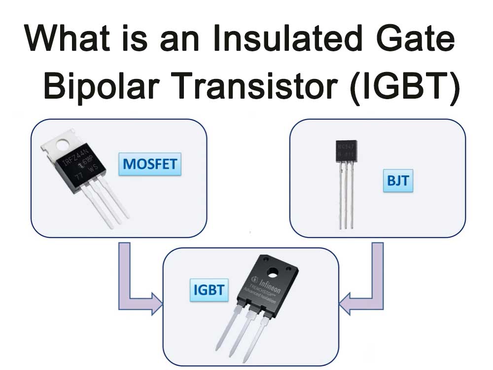
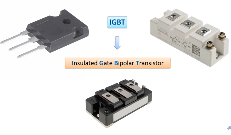
Insulated-Gate Bipolar Transistor (IGBT for short) is a semiconductor device that combines the advantages of power transistor (Giant Transistor (GTR for short)) and power field effect transistor (Power MOSFET).
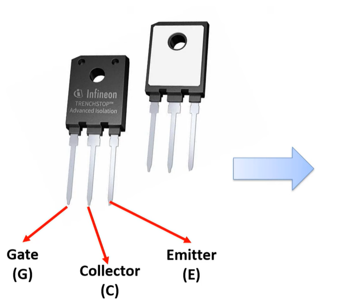
It has good characteristics and applications. The field is very broad. It is also a three-terminal device: gate, collector and emitter.
IGBT combines the advantages of bipolar transistors and field-effect transistors, such as low driving power and low saturation voltage.
Specifically, it consists of a bipolar triode (BJT) and a metal oxide semiconductor field effect transistor (MOSFET), which are packaged through specific circuit bridges to form a modular semiconductor product.
IGBT has conductance modulation capability and has stronger forward current conduction density and lower on-state voltage drop than MOSFET and bipolar transistor.
Its switching characteristics can realize conversion between DC and AC or change the frequency of current. It has the functions of inversion and frequency conversion, and can be used in inverters, frequency converters, switching power supplies, lighting circuits, traction drives and other fields.
Why are insulated gate bipolar transistors needed in PCB circuits?
Insulated gate bipolar transistors (IGBTs) play an important role in PCB circuits for the following reasons:
- It combines the advantages of power transistors and power field effect transistors, has good characteristics, and has a wide range of applications.
- It is a three-terminal device with gate, collector and emitter. It can use high input impedance for voltage control and has high forward current density.
- In terms of working principle, when a positive voltage is applied to the gate, a channel is formed in the MOSFET and provides base current for the bipolar transistor, thereby turning on the IGBT. At this time, the holes injected from the emitter region into the N-region modulate the conductance of the N-region, reducing the resistance RMOD of the N-drift region, so that the high withstand voltage IGBT also has low on-voltage characteristics.
Therefore, in PCB circuits, insulated gate bipolar transistors (IGBTs) are mainly used as a power electronic device and play an important role in motor control, high-voltage direct current transmission, rail transportation and other fields.
Principle analysis
The insulated gate bipolar transistor (IGBT) is a composite device that works by combining the characteristics of a bipolar transistor (BJT) and a field effect transistor (MOSFET). IGBT is mainly composed of a MOSFET and a PNP transistor. These two components are integrated through special structural design and process.
In IGBT, MOSFET acts as a driver to control the on and off of the entire device. When a positive voltage is applied to the gate, the electric field in the MOSFET forms a conductive channel, providing base current to the PNP transistor, thereby turning on the IGBT. At this time, the holes injected from the P+ region into the N- region modulate the conductance of the N- region, reducing the resistance RMOD of the N- region, so that the high-voltage IGBT also has low on-voltage characteristics.
When a negative voltage is applied to the gate, the channel of the MOSFET disappears, the PNP transistor is cut off, and the IGBT is in the off state. It can be seen that the driving principle of IGBT is basically the same as that of MOSFET tube. Since the equivalent bipolar transistor is the dominant component of IGBT, IGBT has large current transmission capability.
In addition, IGBT is similar in structure to power MOSFET, except that an additional P+ type layer is added between the drain of the original power MOSFET and the substrate. This structure allows the IGBT to have higher input impedance and greater current transfer capability. At the same time, because IGBT has a conductance modulation effect, it can reduce the resistance RMOD of the drift region in the conduction state, thereby improving the conduction efficiency of the device.
Structure and composition
The structure of an insulated gate bipolar transistor (IGBT) consists of a control pin, a drain, a source and an insulated gate. Among them, the insulating gate is composed of an oxide capacitor, which can control the size of the current, thereby controlling the voltage and current.
In terms of specific structure, the N-channel enhancement structure of IGBT includes an N+ region called the source region, the electrode attached to it is called the source (i.e., the emitter E), and the N base is called the drain region.
The control area of the device is the gate area, and the electrode attached to it is called the gate (ie, gate G). A channel is formed close to the gate boundary.
The P-type region (including P+ and P- regions) between the C and E poles is called the subchannel region. The P+ region on the other side of the drain region is called the drain injector.
Application areas
Insulated gate bipolar transistor (IGBT) is a very important semiconductor device with excellent electrical properties and wide range of applications. The following are some application areas of IGBT:
Power system
In power systems, IGBTs are widely used in smart grids, renewable energy grid integration, reactive power compensation, active filtering and other fields. It can realize the conversion and regulation of electric energy and ensure the stable operation of the power system.
Motor control
Due to the characteristics of high efficiency, high speed and high reliability, IGBT is widely used in the field of motor control. For example, IGBT can be seen in motor control systems in electric vehicles, industrial motors, household appliances and other fields.
New energy vehicles
New energy vehicles are one of the important application areas of IGBT. In new energy vehicles such as electric vehicles, hybrid vehicles, and hydrogen fuel cell vehicles, IGBTs are used to control battery management, motor drive, and vehicle air conditioning.
Rail transit
In the field of rail transit, IGBT is widely used in train traction, auxiliary power supply and control systems.
Smart home
In the field of smart home, IGBT is used in motor control and energy-saving circuits of household appliances such as air conditioners, refrigerators, and washing machines.
Industrial automation
In the field of industrial automation, IGBT is used in motor drives, control systems and energy conversion of CNC machine tools, automated production lines, industrial robots and other equipment and systems.
New energy
In new energy fields such as wind energy and solar energy, IGBT is used to convert and regulate energy and improve energy utilization efficiency.
In short, the application fields of IGBT are very wide, involving many fields such as electric power, transportation, new energy, smart home and so on.
With the continuous advancement of science and technology and the growing demand for applications, the application prospects of IGBT will become broader.
Insulated Gate Bipolar Transistor Advantages and Disadvantages
IGBT advantages
- High voltage withstand capability: The operating voltage of IGBT can reach thousands of volts, which is much higher than the limit of general bipolar transistors.
- High current carrying capacity: The current carrying capacity of IGBT can reach hundreds of amperes, which is much higher than the limit of general field effect transistors.
- Fast switching speed: The switching speed of IGBT can reach the microsecond level, which is much faster than ordinary bipolar transistors, which gives it an advantage in high-frequency circuits.
- It overcomes the base current loophole of traditional bipolar transistors, improves the current amplification factor, and enhances the current driving capability.
- The sophisticated design overcomes the nonlinear problems of traditional transistors, resulting in smaller signal distortion and high accuracy.
- The capacitance between the insulation grid and the tube body has a strong coupling effect, with good stability and high reliability.
IGBT disadvantages
- Large conduction voltage drop: Due to the special structure of IGBT, its conduction voltage drop is larger than that of ordinary bipolar transistors, which will lead to increased power loss.
- Large switching loss: Due to the zero-voltage switching and zero-current turn-off characteristics of IGBT, it easily generates a large amount of heat during the switching process, thereby increasing switching losses.
MOSFET Vs. IGBT
Both MOSFET and IGBT are commonly used power semiconductor devices in the electronic field. They have some differences in structure, working principle and application fields.
First of all, from the perspective of structure and working principle, the difference between MOSFET and IGBT is mainly reflected in the internal structure. MOSFET can usually achieve a large current, up to KA level, but its voltage resistance is not as strong as IGBT. IGBT has higher efficiency when producing high voltage and large current, and its current and voltage can be very large.
Secondly, from the perspective of application fields, MOSFET is usually used in high-frequency power supply fields such as switching power supplies, ballasts, high-frequency induction heating, high-frequency inverter welding machines, and communication power supplies. IGBTs are mainly used in welding machines, inverters, frequency converters, electroplating electrolytic power supplies, ultrasonic induction heating and other fields.
In addition, in terms of switching speed, the switching speed of MOSFET is relatively fast, which can reach hundreds of KHZ, or even MHZ and dozens of MHZ, while the switching speed of IGBT is relatively slow, and the current hard switching speed can reach 100KHZ.
Taken together, MOSFET and IGBT each have their own advantages and disadvantages, and which device to choose depends on the specific application requirements.
IGBT comparison table
| Device characteristic | Power BJT | Power MOSFET | IGBT |
|---|---|---|---|
| Voltage rating | High <1 kV | High <1 kV | Very high >1 kV |
| Current rating | High <500 A | Low <200 A | High >500 A |
| Input drive | Current ratio hFE ~ 20–200 | Voltage VGS ~ 3–10 V | Voltage VGE ~ 4–8 V |
| Input impedance | Low | High | High |
| Output impedance | Low | Medium | Low |
| Switching speed | Slow (µs) | Fast (ns) | Medium |
| Cost | Low | Medium | High |
What is IGBT failure mechanism?
The failure mechanisms of IGBT (Insulated Gate Bipolar Transistor) mainly include the following:
- Thermal stress failure: Due to the existence of different sizes of isotropic stresses between material interfaces under different temperature conditions, the IGBT layers working in a periodic switching state generate interactive periodic shear stress. As the aging of the device deepens, thermal stress shear force is generated between the multi-layer materials of the IGBT package when the module is in the switching state. Its effect breaks the stress balance inside the module, causing the internal structure of the IGBT to change, causing bending deformation, breakage, etc. Metal effects such as lead falling off will eventually cause the device to fail.
- Over-electrical stress failure: Excessive voltage or current causes excessive power loss of the device, causing local overheating. When abnormally large currents and voltages are superimposed at the same time, transient heating can cause IGBT failure.
- Failure of welded IGBT modules: The shedding of bonding wires is the most likely to occur. Some data show that the shedding of wires can account for about 70% of IGBT module failures. This is mainly due to the fact that after the lead is repeatedly subjected to thermal stress for a long time to a certain extent, arc flashover occurs when current flows rapidly, which will cause the bonding wire to peel off.
- Fatigue failure: This is due to the fact that ultrasonic vibration causes cracks at the root of the aluminum bonding wire during the welding process, and the fracture process is slower than the aluminum bonding wire falling off.
What are the detection methods for IGBT failure?
The main methods for detecting IGBT failure are as follows:
- Appearance inspection: By observing the appearance of the IGBT module, check whether there are obvious burns, cracks, discoloration, etc., and whether labels, connections, etc. are complete.
- Functional test: By testing the input, output voltage and current of the IGBT module, as well as the voltage and current changes in the switching state and other parameters, determine whether its function is normal.
- Static test: By measuring the key parameters of the IGBT module, such as gate-emitter voltage, collector-emitter voltage, drain-emitter current, etc., determine whether it is within the normal range.
- Dynamic test: In the dynamic test, the actual working state will be simulated, and the IGBT module will be subjected to switching test, overload test, etc. to observe whether its dynamic performance is normal.
- Temperature test: By measuring the performance parameters of the IGBT module at different temperatures, evaluate its stability and reliability at different temperatures.
- Electromagnetic compatibility testing: Conduct electromagnetic compatibility testing on IGBT modules to check whether they comply with relevant standards and specifications.
- Failure analysis: Conduct in-depth analysis of the failed IGBT module, observe its surface and internal structure through microscopes, X-rays, scanning electron microscopes and other means to determine the cause of the failure.
What are the consequences of IGBT failure?
IGBT failure can have serious consequences for the equipment.
If IGBT fails and causes other problems, it may cause serious failures in production, environment and society. For example, it can cause serious equipment failure at the least, cause the company to stop production and even cause catastrophic accidents at worst. With the promotion of concepts such as energy conservation and environmental protection, there will be more and more demands for IGBT power modules in the market. Therefore, studying the failure of IGBT power modules is an important topic.
In addition, IGBT failure will also affect the reliability, operating status and life of the device. If the health status of the device during operation cannot be effectively evaluated and related faults are handled in a timely manner, the entire system may not be able to operate safely and reliably, or even cause major accidents such as casualties.
Therefore, in order to ensure that the power converter can operate stably and reliably for a long time during service, avoid causing serious safety accidents and major economic losses, and at the same time ensure the targeted maintenance of IGBT power modules and improve maintenance efficiency, the health status of the device must be monitored. Accurate and effective monitoring and evaluation.
What is the reason for IGBT failure?
There are many reasons for IGBT failure, including the following:
- Overheating: Overheating will cause the internal temperature of the IGBT to increase, thereby damaging the collector. Overheating may be caused by poor heat dissipation, excessive current, persistent short circuit, etc. If the chip temperature exceeds the silicon intrinsic temperature (about 250°C), the device will lose its blocking capability and the gate control will not be able to protect it, resulting in IGBT failure.
- Exceeding the shutdown safe working area: Exceeding the shutdown safe working area will cause a holding effect, increase the collector current, produce excessive power consumption, and cause device failure.
- Transient overcurrent: Transient overcurrent will put an excessive burden on the IGBT, increasing its burden, thus increasing the burden on the IGBT, which may eventually lead to IGBT failure.
- Overvoltage: Overvoltage will cause collector and emitter breakdown or cause gate and emitter breakdown, which will lead to IGBT failure.
- Manufacturing process problems: Manufacturing process problems may also cause IGBT failure, such as chip defects, uneven base area width, etc.
- Improper use: Improper use may also cause IGBT failure, such as incorrect driving voltage or current, incorrect parallel configuration, etc.
To sum up, in order to ensure the reliability and stability of IGBT, a series of measures need to be taken to avoid these failure causes. For example, strengthen the heat dissipation design, select the appropriate drive circuit, avoid exceeding the shutdown safe working area, and design the circuit structure rationally. At the same time, it is also necessary to strengthen the manufacturing process control of the device and the maintenance during use.
What is the difference between an insulated gate bipolar transistor and a power transistor?
Insulated gate bipolar transistors (IGBTs) and power transistors (Power Transistors) differ significantly in several aspects:
- Current control type: IGBT is a current control device, and the current of its drive circuit needs to be large enough. The power transistor is a voltage-type control device. As long as the applied voltage between the gate and the source exceeds its threshold voltage, it will turn on.
- Input impedance: The input impedance of the power transistor is large, which makes the drive circuit structure simple and the drive power small. In contrast, the driving circuit of IGBT is relatively complex and requires large driving power.
In summary, there are significant differences between IGBTs and power transistors in terms of current control type and input impedance.
Insulated Gate Bipolar Transistor FAQs
IGBT, short for insulated gate bipolar transistor, is a three-terminal semiconductor switching device that can be used for efficient and fast switching in a variety of electronic equipment.
IGBT consists of three terminals (collector, emitter and gate) all attached with metal layers. However, the metal material on the gate terminal has a silicon dioxide layer. It is a four-layer semiconductor device implemented by combining PNP and NPN transistors.
IGBT has a wide range of application fields, including power systems, motor control, new energy vehicles, rail transit, smart homes, industrial automation and new energy.
The four-layer transistor structure of IGBT is a special power semiconductor transistor consisting of 4 alternating P-N-P-N layers. This structure makes the IGBT have excellent electrical performance and can achieve efficient and fast control and switching.
The failure of IGBT can be detected through various methods, such as appearance inspection, functional test, static test, dynamic test, temperature test, electromagnetic compatibility test and failure analysis, etc. These methods can help determine whether the IGBT is working properly and identify potential problems.
The basic characteristics of IGBT include static characteristics (transfer characteristics) and output characteristics (volt-ampere characteristics). The transfer characteristics describe the relationship between the collector current IC and the gate-emitter voltage UGE, while the output characteristics describe the relationship between the collector current IC and the collector-emitter voltage UCE when the gate-emitter voltage is used as a reference variable.