
Hello everyone, my name is AnWen, and today we will share with you the solar charging control PCB design.
In the future, I will share with you DFM manufacturability analysis, PCB design, DFM tools, circuit design and other related knowledge here. Please give me your advice.
What I want to share with you today is: PCB project – MPPT solar charge controller using LT3652. (Attached with project schematic diagram + project information (Gerber) file, please remember to send me a private message to receive it)
Almost every solar-based system has a battery associated with it that must be charged from the sun, and the energy from the battery is used to drive the load. But to use solar panels to charge batteries, a better option is MPPT or maximum power point tracker topology, which has better accuracy than PWM controlled charger.
Working principle of MPPT solar charge controller
MPPT is an algorithm commonly used in solar chargers. The charge controller measures the output voltage of the panel and the battery voltage. By taking these two data, comparing them to determine the optimal power that the panel can provide to charge the battery. .
In any case, whether the sunlight conditions are good or poor, the MPPT charge controller uses this maximum power output factor and converts it into the optimal charging voltage and current for the battery. Whenever the power output of the solar panel decreases, the battery charging current also decreases.
Therefore, in low sunlight conditions, the battery is continuously charged based on the output of the solar panel. This doesn’t usually happen with regular solar chargers. Because every solar panel comes with a maximum output current rating and a short circuit rating.
MPPT is approximately 90%-95% efficient in conversion. Efficiency then also depends on solar driver temperature, battery temperature, solar panel mass and conversion efficiency.
In this project, build a solar MPPT charger for lithium batteries.
Design MPPT Charger
Will charge 2P2S battery (6.4-8.4V)
Charging current is 600mA
There will be an additional charging option using an adapter
List of components required to build the MPPT controller
LT3652 driver
1N5819 – 3 pcs.
10k pot
10uF capacitor – 2 pcs
Green LED
Orange LED
220k resistor
330k resistor
200k resistor
68uH inductor
1uF capacitor
100 uF capacitor – 2 pcs.
Battery – 7.4V
2 1k resistors
Barrel socket
MPPT solar charger circuit diagram
The complete solar charge controller circuit is shown below:
This circuit uses the LT3652, a complete monolithic step-down battery charger that operates from an input voltage range of 4.95V to 32V. Therefore, the maximum input range for solar and adapter is 4.95V to 32V.
The LT3652 provides a constant current/constant voltage charging feature that can be programmed through a current sense resistor for a maximum charge current of 2A.
Output Section: The charger uses a 3.3V float voltage feedback reference so any desired battery float voltage up to 14.4V can be programmed using a resistor divider.
The LT3652 also contains a programmable safety timer using a simple capacitor, which is used to terminate charging after a desired time, useful for detecting battery failure.
The LT3652 requires MPPT setting, and one of the potentiometers can be used to set the MPPT point. When the LT3652 is powered by a solar panel, the input regulation loop is used to maintain the panel at peak output power. How to maintain regulation depends on the MPPT setting potentiometer.
MPPT solar charger value setting
- Battery voltage setting
VR1 is used to set the MPPT point, R2, R3, and R4 are used to set the 2S battery charging voltage (8.4V). The formula for setting the battery voltage is as follows:
RFB1 = (VBAT(FLT) • 2.5 • 10 5 )/3.3
RFB2 = (RFB1 • (2.5 • 10 5 ))/(RFB1 – (2.5 • 10 5 )) (set battery voltage formula)
- Timer settings
Capacitor C2 is used to set the charging timer, which can be set using the following formula:
tEOC = CTIMER • 4.4 • 10 6 (in hours) (set timer)
D3 and C3 are the boost diode and boost capacitor that drive the internal switch and promote saturation of the switching transistor. The boost pin operates from 0V to 8.5V.
- Charging current setting
R5 and R6 are parallel current sensing resistors, and the charging current can be calculated using the following formula:
RSENSE = 0.1/ICHG(MAX) (set charging current)
The current sense resistors in the schematic are chosen to be 0.5 Ω and 0.22 Ω, which are combined in parallel to produce 0.15 Ω. Using the above formula it will produce a charging current of almost 0.66A, C4, C5 and C6 are the output filter capacitors.
How the DC barrel jack is connected: If you plug the adapter jack into the adapter socket, the solar panel will disconnect. D1 will protect the solar panel or adapter from reverse current flow during no charging conditions.
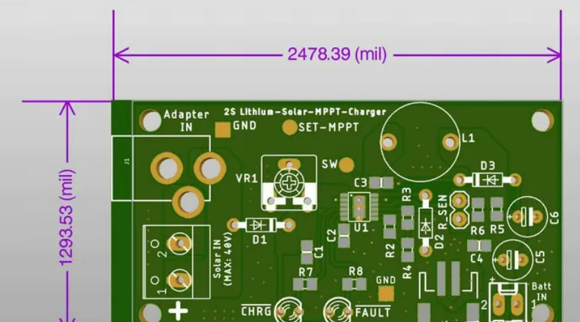
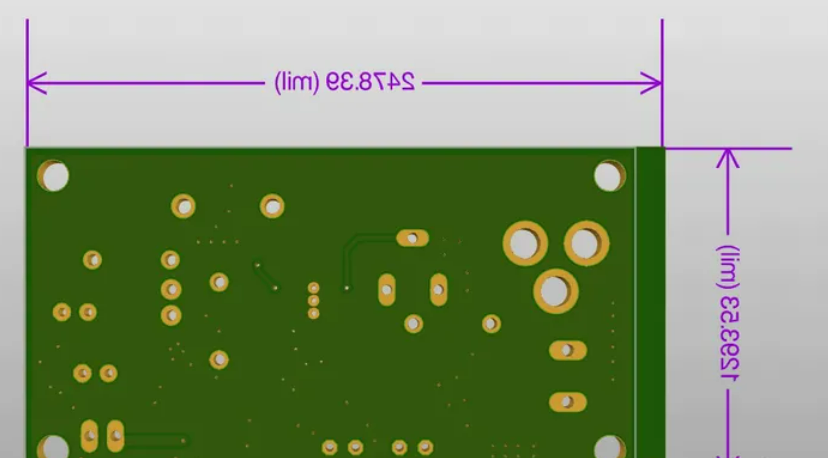
Solar Charge Controller PCB Design
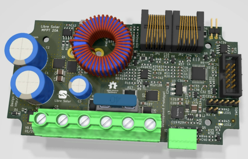
For the MMPT circuit discussed above, the MPPT charger controller 3D PCB diagram is designed, as shown below:
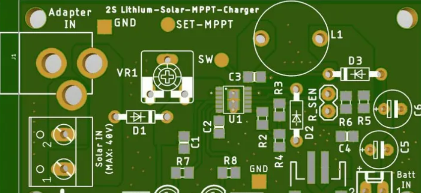
The design has a GND copper plane with appropriate connecting vias, the LT3652 requires an adequate PCB heatsink, which is created using a GND copper plane and placing the vias in the solder plane.
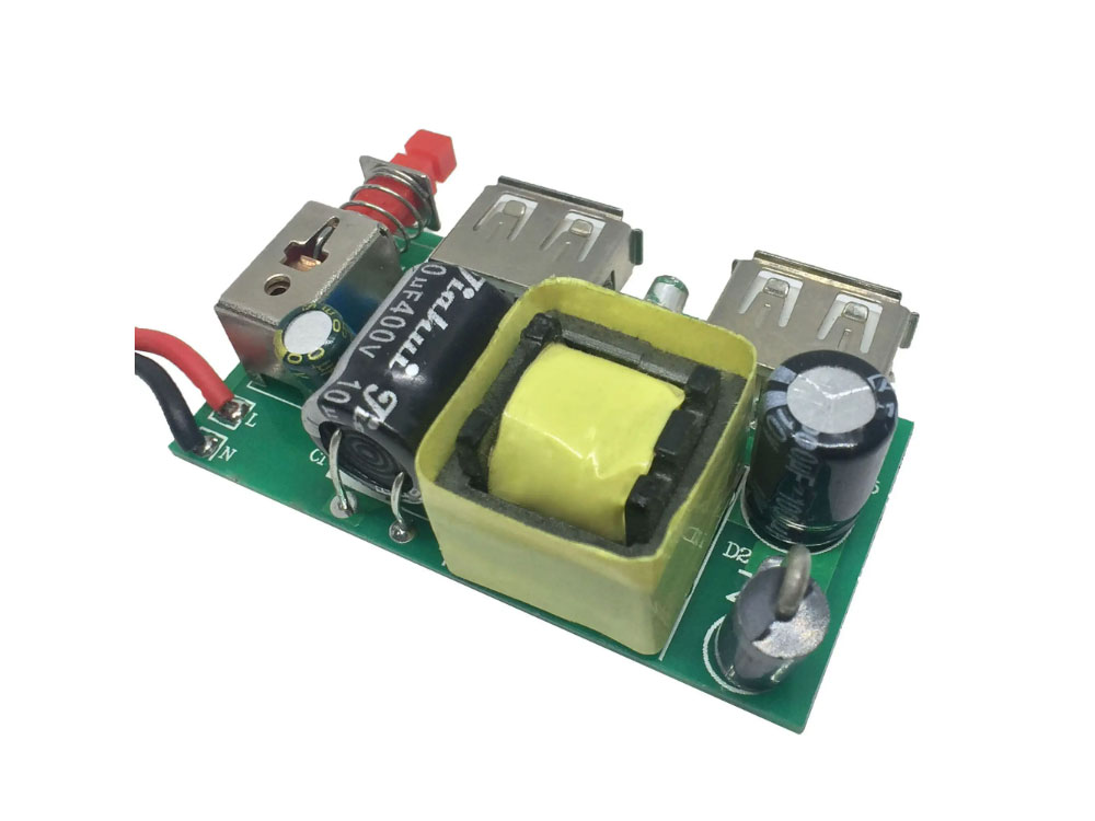
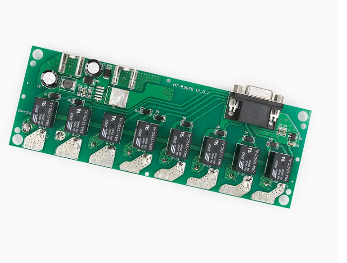
Assembling the MPPT Solar Charge Controller
The physical picture of the MPPT charger controller PCB is shown below:
Testing the MPPT Solar Charger
To test the circuit, a solar panel rated 18V .56A was used. The picture below is the detailed specifications of the solar panel.
Detailed specifications of solar panels
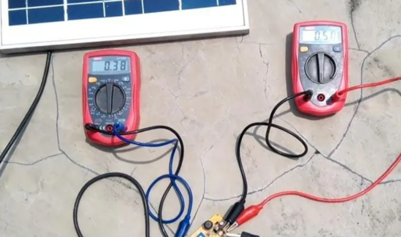
The complete circuit was tested under mild sunlight conditions using a 2P2S battery (8.4V 4000mAH) battery for charging –
After everything is connected, set the MPPT when the sun conditions are right and control the potentiometer until the charging LED starts glowing and the circuit is working smoothly.
Frequently Asked Questions
Issues that need attention in solar charging control PCB design include power management, current and voltage stability, charging protection, safety performance, energy efficiency ratio, component layout and wiring, etc.
To ensure the stability and reliability of solar charging control PCB design, it is necessary to select appropriate components, conduct sufficient testing and verification, and use technical means such as multi-layer PCB board design to improve the electrical and mechanical properties of the PCB board.
In terms of component layout and wiring, it is necessary to consider the arrangement order of components, heat dissipation performance, electromagnetic interference and other factors, and rationally plan component layout and wiring to reduce electromagnetic interference and improve heat dissipation performance.
In terms of safety performance, it is necessary to consider issues such as overload protection, short-circuit protection, temperature protection, etc., and take corresponding protective measures to ensure the safety and stability of the circuit.
Energy efficiency ratio is one of the important indicators for evaluating solar charging control PCB design. It can be evaluated through experimental testing and simulation analysis to improve the overall performance of the solar charging control system.
Choosing suitable components is one of the keys to designing solar charging control PCB. It is necessary to consider the performance parameters, reliability, cost and other factors of the components to select components with stable quality and reliable performance.
Solar charging control panel is an electronic device used in solar photovoltaic systems to control the charging and discharging process. Its main function is to convert the electric energy generated by the solar panel into direct current, and charge the battery through the control circuit, while preventing overcharging and protecting the battery.
Common components of solar charging control panels include solar panels, batteries, charging control circuits, discharge control circuits and protection circuits. Among them, the charge control circuit and the discharge control circuit are the core components, used to realize automatic charge and discharge control and extend battery life.
The working principle of the solar charging control panel is to use the photovoltaic effect principle to convert solar energy into electrical energy, and charge the battery through the charging control circuit. When the sun shines on the solar panel, the panel will generate direct current. The charging control circuit will adjust the charging current through PWM (pulse width modulation) according to the battery’s power and charging status to achieve automatic charge and discharge control. At the same time, the protection circuit can prevent the battery from overcharging and over-discharging to extend the service life of the battery.
When choosing a suitable solar charging control panel, you need to consider the following aspects:
Voltage and current requirements: Select the appropriate control board according to the voltage and current requirements of the load to ensure sufficient power supply.
Power requirements: Select an appropriate control board according to the power requirements of the load to ensure sufficient power output.
Charging method: Choose the appropriate charging method according to the actual situation, such as PWM constant current charging, PWM constant voltage charging, etc.
Protection function: Choose a control board with overcharge, over-discharge, over-current, short-circuit and other protection functions to ensure the safe and stable operation of the system.
Installation environment: Consider the impact of the installation environment on the control panel, such as temperature, humidity, sun protection, etc., and select a control panel with suitable environmental conditions.