Discussion on the special structure of biased transistors in current sources

Discussion on the special structure of biased transistors in current sources

Introduction

In modern electronics, current sources and bias transistors play a vital role. These basic components are widely used in various electronic devices such as amplifiers, oscillators, logic gates, etc.

However, there are still many unsolved mysteries in academia and industry regarding the special structure of biased transistors in current sources. This article will detail the special structures of biased transistors and how these structures affect the performance of current sources.

Basic structure and working principle of biased transistor

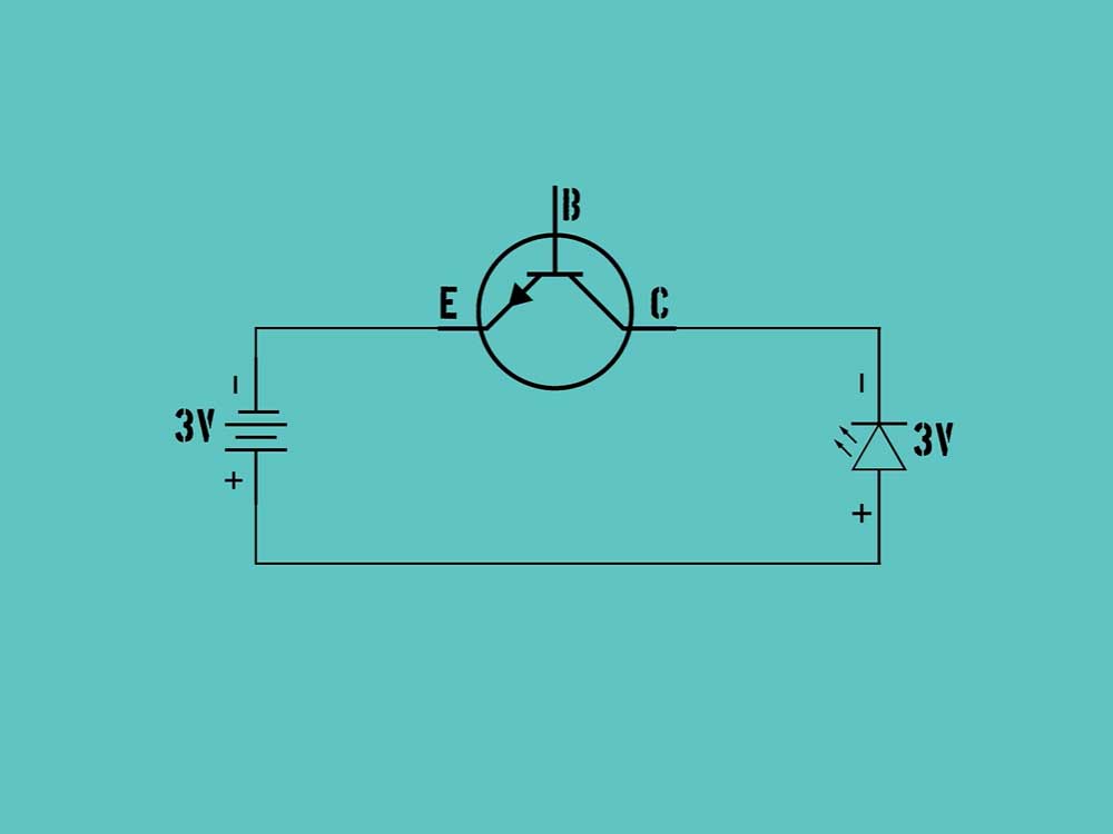
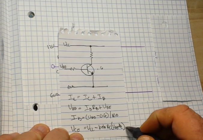
First, we need to understand the basic structure of a biased transistor and how it works. A triode is an electronic device made of a semiconductor material (usually silicon or germanium) and has three electrodes: base (B), collector (C) and emitter (E). In a current source, the main function of a bias transistor is to provide and regulate a constant current. This current can be used as the operating current for amplifiers, oscillators, or other electronic devices.

Transistor practical application cases - Npn transistor practical application cases

Effect of special structure on current source performance

Special structure refers to additional designs or modifications introduced during the manufacturing process of a triode to improve its performance or meet specific application needs. These special structures may include: base region doping gradient design, emitter shape adjustment, collector structure design, etc.

  1. Base region doping gradient design: The base region is the part of the triode that connects the base and collector. By changing the doping concentration of the base region, the size and distribution of the collector current can be affected, further affecting the output stability of the current source.
  2. Emitter shape adjustment: The emitter is the part of the triode that connects the base and collector. Changing the shape of the emitter, such as increasing the emitter area or introducing a groove structure, can optimize the current distribution and improve the efficiency of the current source.
  3. Collector structure design: The collector is the electrode that collects electrons in the triode. By changing the structure of the collector, such as increasing the length of the collector or changing the width of the collector, the cutoff frequency and maximum oscillation frequency of the triode can be adjusted, thereby affecting the bandwidth and stability of the current source.
Working structure diagram in transistor circuit

Practical application case analysis

To gain a deeper understanding of how these special structures affect the performance of current sources, we will analyze some real-world application cases. For example, in audio amplifiers, using triodes with special emitter designs can reduce harmonic distortion and improve sound quality; in high-speed digital circuits, using triodes with optimized collector structures can reduce signal delay and increase the operating frequency of the circuit.

Future research directions and prospects

With the continuous development of science and technology, the research on the special structure of the biased transistor in the current source is also in-depth. Future research directions may include: exploring the application of new materials in biased triodes, developing smart triodes with adaptive functions, and studying the collaborative working mechanism of triodes and other electronic components. Through these studies, we are expected to further improve the performance of current sources and promote the development of electronic technology.

Electronic devices and electronic components assembled in PCB projects

In conclusion

This article conducts an in-depth discussion of the special structure of the biased transistor in the current source and analyzes the impact of the special structure on the performance of the current source.

By understanding these effects, we can better design and optimize current sources in electronic devices, improving their performance and stability.

At the same time, we also see broad prospects for future research, which will have a profound impact on the development of electronic technology.

Frequently Asked Questions

What is a biased transistor?

A biased transistor is an electronic device made of a semiconductor material (usually silicon or germanium) with three electrodes: base (B), collector (C), and emitter (E). In current sources, the main function of the bias transistor is to provide and regulate a constant current, which can be used as the operating current of amplifiers, oscillators or other electronic devices.

What impact does the special structure have on current source performance?

Special structure refers to additional designs or modifications introduced during the manufacturing process of a triode to improve its performance or meet specific application needs. These special structures may include base region doping gradient design, emitter shape adjustment, collector structure design, etc. These special structures can affect the performance of the current source, such as output stability, efficiency, bandwidth and stability.

How to understand the impact of base doping gradient design on current source performance?

The doping gradient design of the base region refers to affecting the size and distribution of the collector current by changing the doping concentration of the base region. By optimizing the doping concentration of the base region, the output stability of the current source can be further optimized. This design enables the current source to maintain a stable output under different operating conditions, thereby improving its performance.

How does emitter shape adjustment affect current source performance?

Emitter shape adjustment refers to changing the shape of the emitter, such as increasing the emitter area or introducing a groove structure. By optimizing the shape of the emitter, the efficiency of the current source can be further optimized. This design can improve the uniformity of current distribution and reduce energy loss, thereby improving the efficiency of the current source.

How does collector structure design affect current source performance?

Collector structure design refers to changing the structure of the collector, such as increasing the length of the collector or changing the width of the collector. This design can adjust the cutoff frequency and maximum oscillation frequency of the triode, thereby affecting the bandwidth and stability of the current source. By optimizing the structural design of the collector, the bandwidth and stability of the current source can be improved, allowing it to maintain stable output under different operating conditions.

How to choose a suitable bias transistor in practical applications?

In practical applications, selecting a suitable biased transistor requires considering its special structure, performance parameters, and application requirements. Based on the circuit requirements and comparison of performance parameters, a transistor with an appropriate special structure can be selected to optimize the performance of the current source. In addition, other parameters of the transistor need to be considered, such as breakdown voltage, collector current and noise.

Selection of common electronic components based on EMC

Selection of common electronic components based on EMC

With the development of science and technology and the increasing complexity of electronic systems, electromagnetic compatibility (EMC) has become an important factor that must be considered in the design of electronic systems.

In the selection process of electronic components, in addition to conventional performance parameters and cost considerations, EMC characteristics have also become a key decision-making factor. This article will introduce in detail the selection of common electronic components based on EMC.

Introduction to EMC characteristics of electronic components

Selection of common electronic components based on EMC

Electromagnetic compatibility (EMC) refers to the ability of electronic equipment to operate normally in an electromagnetic environment. An electronic system with good EMC characteristics can work stably in various electromagnetic interference (EMI) environments while avoiding electromagnetic interference to other systems. As the basic components of electronic systems, electronic components’ EMC characteristics are crucial to the performance of the entire system.

Common electronic component selection principles based on EMC

Common electronic component selection principles based on EMC
  1. Choose components with low electromagnetic radiation: When selecting electronic components, priority should be given to components that generate small electromagnetic radiation. This can reduce the interference of components on other systems and improve the stability of the system.
  2. Choose components with high electromagnetic immunity: Choosing components with high resistance to external electromagnetic interference can enhance the stability of the system in complex electromagnetic environments.
  3. Consider packaging and layout: When selecting electronic components, you should also consider their packaging and layout. Proper packaging and layout can reduce the risk of electromagnetic radiation and interference.
  4. Comprehensive consideration of cost and performance: Although EMC characteristics are crucial to electronic systems, the cost and performance of components must also be considered comprehensively. On the premise of meeting system requirements, select components with high cost performance.
  5. Reference standards and regulations: When selecting electronic components, you should ensure that the selected components comply with relevant national and international electromagnetic compatibility standards and regulations.

EMC characteristics of common ordinary electronic components

  1. Resistors: Choosing low-resistance, low-noise resistors can effectively reduce electromagnetic interference in the circuit. Additionally, metal film resistors generally have better EMC characteristics.
  2. Capacitor: When selecting a capacitor, attention should be paid to its ESL (equivalent series inductance) and ESR (equivalent series resistance) parameters. Capacitors with low ESL and ESR help reduce electromagnetic interference in circuits.
  3. Inductor: The inductor should be selected with high magnetic permeability and low loss to reduce electromagnetic interference and improve efficiency.
  4. Diodes and transistors: These semiconductor devices should be selected with low noise and low distortion characteristics to reduce the electromagnetic interference they generate.
  5. Integrated circuits (ICs): Modern integrated circuits usually have built-in EMC protection functions, but you still need to pay attention to their EMC performance indicators when selecting.

Precautions in Practical Application

  1. Understand the application scenario: When selecting electronic components, you should fully understand the electromagnetic environment characteristics of its application scenario in order to select suitable components in a targeted manner.
  2. Reference professional information: During the selection process, you can refer to EMC test reports and data published by professional organizations to more accurately evaluate the EMC performance of components.
  3. Collaborative design: While selecting electronic components, you should also pay attention to the EMC design of the entire system, such as cable management, grounding strategies, etc., to achieve optimal overall performance.
  4. Verification and testing: After selecting components, it is recommended to conduct actual verification and testing to ensure that they can work properly in the expected electromagnetic environment.
The application of EMC design in the selection of electronic components

The application of EMC design in the selection of electronic components

In the selection process of electronic components, EMC design is a crucial link. Through reasonable EMC design, the system’s requirements for electromagnetic compatibility can be better met and the performance and stability of electronic equipment can be improved.

  1. Understand the electromagnetic environment: Before selecting electronic components, you should fully understand the electromagnetic environment of the application scenario, including the source of electromagnetic interference, frequency range, amplitude, etc., so that you can select appropriate components in a targeted manner.
  2. Develop EMC indicators: Based on system requirements and electromagnetic environment, formulate clear EMC indicators as an important basis for selecting electronic components.
  3. Optimize circuit design: During the circuit design stage, EMC issues should be fully considered, circuit layout and wiring should be optimized, and electromagnetic radiation and interference should be reduced.
  4. Select appropriate filters: According to needs, select appropriate filters, such as power supply filters, signal line filters, etc., to reduce the impact of electromagnetic interference.
  5. Grounding design: Reasonable grounding design can effectively improve the electromagnetic anti-interference ability of the system and reduce the impact of ground wire noise on the system.
  6. Shielding measures: For key parts or sensitive components, shielding measures, such as metal boxes, metal mesh, etc., can be used to reduce the impact of external electromagnetic interference.
  7. Simulation and testing: Verify the feasibility and effectiveness of the design through electromagnetic field simulation and actual testing, and further optimize the selection and configuration of components.

Future trends

With the continuous advancement of electronic technology and the broadening of application fields, the EMC characteristics of electronic components will receive more and more attention. In the future, new components with excellent EMC performance will continue to emerge, providing more choices for the efficient and stable operation of electronic systems.

At the same time, with the continuous improvement of electromagnetic compatibility standards and people’s increasing awareness of environmental protection, green electronic components with low radiation and low interference will become the future development trend.

Commonly used electronic components for EMC

In short, the selection of common electronic components based on EMC is a complex process that comprehensively considers performance, cost, electromagnetic compatibility and environmental protection requirements.

By deeply understanding the EMC characteristics of electronic components, rationally applying EMC design principles, and paying close attention to future development trends, we can better meet the stability and reliability requirements of electronic systems and promote the continuous progress and innovation of electronic technology.

Frequently Asked Questions

What is electromagnetic compatibility (EMC)?

Electromagnetic compatibility (EMC) refers to the ability of electronic equipment to operate normally in an electromagnetic environment. An electronic system with good EMC characteristics can work stably in various electromagnetic interference (EMI) environments while avoiding electromagnetic interference to other systems.

What are the principles for selecting common electronic components based on EMC?

The principles for selecting common electronic components based on EMC include: selecting components with low electromagnetic radiation, selecting components with high electromagnetic immunity, considering packaging and layout, comprehensive consideration of cost and performance, reference standards and regulations.

What are the EMC characteristics of common ordinary electronic components?

When selecting electronic components such as resistors, capacitors, inductors, diodes, transistors and integrated circuits, attention should be paid to their EMC characteristics, such as low resistance, low noise, high magnetic permeability, low loss, etc.

In practical applications, how to apply EMC design principles to select electronic components?

Understand the electromagnetic environment characteristics of the application scenario, formulate clear EMC indicators, optimize circuit design and grounding design, select appropriate filters and shielding measures, and verify the feasibility and effectiveness of the design through simulation and testing.

How to filter electronic components?

Filtering of electronic components can be achieved by using filters. Filters can be divided into RC filters, LC filters and crystal filters according to their working principles. As needed, appropriate filters can be selected to reduce the effects of electromagnetic interference.

What is a power line filter?

A power line filter is an electronic component used to suppress the propagation of conducted emission currents along power lines. It usually consists of a filter circuit composed of inductors and capacitors, which can filter out electromagnetic interference signals on power lines and protect electronic equipment from electromagnetic interference.

How to choose the right power line filter?

When selecting a power line filter, you need to consider its insertion loss, rated current, voltage, effective frequency range and other parameters to select the appropriate model. In addition, the way the filter is mounted and the size and weight requirements of the electronics also need to be considered.

What are the installation methods for power line filters?

Power line filter installation methods include series and parallel. Series filters are usually connected directly in series on the power line and are suitable for filtering multiple devices. The parallel filter is connected in parallel to the power input end of the device and is suitable for filtering a single device.

Failure analysis and application of electronic components

Failure analysis and application of electronic components

Failure analysis and application of electronic components is a key link to ensure the reliability and life of electronic products.

By analyzing failed electronic components, we can gain an in-depth understanding of their failure mechanisms, and then take effective measures to improve the reliability and stability of the components. This article will introduce in detail the common methods, application fields and importance of electronic component failure analysis.

Electronic component failure analysis technology pdf

Failure Analysis Methods for Electronic Components

Electronic component failure analysis technology
  1. Appearance inspection: Check the appearance of electronic components visually or under a microscope to see if there is any obvious physical damage or abnormality, such as fracture, deformation, ablation, etc.
  2. Electrical performance testing: Conduct electrical performance testing on electronic components, such as resistance, capacitance, inductance, etc., to detect whether they meet the design requirements.
  3. Structural analysis: Use X-ray, scanning electron microscope (SEM), energy dispersive analysis (EDS) and other means to conduct structural analysis of electronic components to understand their internal structure and material composition.
  4. Chemical analysis: Conduct chemical composition analysis of electronic components through chemical dissolution, spectral analysis, mass spectrometry and other methods to determine their chemical composition and impurity content.
  5. Environmental testing: Electronic components are tested in harsh environments such as high temperature, low temperature, humidity, salt spray, etc. to evaluate their adaptability and reliability.
  6. Failure mode and effect analysis (FMEA): Conduct failure mode and effect analysis on failed electronic components to determine the failure mode, failure cause and failure consequences, and propose corresponding improvement measures.

Electronic component failure analysis application areas

  1. Aerospace field: In the aerospace field, the failure of electronic components may lead to major accidents and catastrophic consequences. Therefore, failure analysis of electronic components is crucial to ensure the safety and reliability of spacecraft.
  2. Military field: A large number of electronic components are used in military equipment, and their reliability is directly related to the success or failure of military operations. Through failure analysis, the weak links of electronic components in military equipment can be found and their reliability can be improved.
  3. Industrial field: In equipment in industrial control, electric power, communications and other fields, the reliability of electronic components directly affects the normal operation of the equipment. Through failure analysis, the design and manufacturing process of electronic components can be optimized and the stability and reliability of the equipment can be improved.
  4. Consumer electronics field: Consumer electronics products such as mobile phones, TVs, computers, etc. use a large number of electronic components. The quality and user experience of these products are closely related to the reliability of electronic components. Through failure analysis, potential problems in the product can be found and product quality and user satisfaction can be improved.
Electronic component failure analysis technology examples

The Importance of Failure Analysis of Electronic Components

  1. Improve product quality: By analyzing failed electronic components, we can identify problems in the design, manufacturing or use process, and optimize product design, manufacturing processes and material selection, thereby improving product quality and reliability.
  2. Extend product life: By analyzing failed electronic components, understanding their failure mechanisms and influencing factors, and taking corresponding improvement measures, the life and stability of the product can be improved.
  3. Reduce maintenance costs: By analyzing failed electronic components, we can quickly and accurately determine the cause of the failure and provide guidance and basis for maintenance, which can shorten the maintenance cycle and reduce maintenance costs.
  4. Improve safety: In some key fields such as aerospace, military equipment, etc., the failure of electronic components may cause serious safety problems. By analyzing failed electronic components, potential safety hazards can be discovered in time and effective measures can be taken to avoid accidents.
  5. Promote technological progress: Through in-depth analysis of failed electronic components, we can understand their shortcomings in performance and reliability and promote the progress and development of related technologies. At the same time, failure analysis can also provide useful reference for the development and application of new materials.

In short, failure analysis of electronic components is of great significance in ensuring the reliability and life of electronic products.

electrical component failure analysis

By analyzing failed electronic components, product design, manufacturing processes and material selection can be optimized, product quality and reliability can be improved, product life can be extended, maintenance costs can be reduced, safety can be improved and technological progress can be promoted.

Electronic component technology manufacturers

E-components is a wholesaler and supplier of electronic components in China. In the field of electronic component failure analysis, there are many well-known manufacturers and technology providers, and E-components is one of them.

Of course, there are other electronic component failure analysis manufacturers; for example, the US JEDEC is an international organization dedicated to formulating and promoting electronic industry standards.

In addition, there are many professional failure analysis institutions, such as Cypress Semiconductor in the United States and Heraeus in Germany.

electronic component problems and solutions

These institutions have rich experience and advanced technology in the field of electronic component failure analysis, and can provide customers with accurate and reliable analysis services.

FAQs on Failure Analysis and Application of Electronic Components

What is electronic component failure analysis?

Electronic component failure analysis is a technical process by which the causes and mechanisms of electronic component failure can be determined. This involves conducting a series of tests and inspections on failed electronic components to collect failure information and analyze it to identify the mode and root cause of the failure.

What is the purpose of electronic component failure analysis?

The purpose of electronic component failure analysis is to improve the reliability and safety of electronic products. Through failure analysis, the cause and mechanism of the failure can be found, so that effective measures can be taken to prevent the recurrence of similar failures and improve the reliability and stability of electronic products.

What are the causes of electronic component failure?

There are many reasons for the failure of electronic components, including manufacturing defects, overload or voltage breakdown, excessive temperature, excessive humidity, radiation, etc. In addition, incorrect use and maintenance can also lead to the failure of electronic components.

How to conduct failure analysis of electronic components?

Failure analysis of electronic components usually includes steps such as visual inspection, electrical performance testing, non-destructive testing and destructive testing. Appearance inspection can find obvious defects or abnormalities; electrical performance testing can detect the electrical performance of failed electronic components; non-destructive testing can check the structure of electronic components through X-ray or ultrasonic methods; destructive testing can further determine Causes and mechanisms of failure.

What are the applications of electronic component failure analysis?

Electronic component failure analysis has applications in many fields, such as electronic product manufacturing, quality control, product maintenance, and reliability engineering. In electronic product manufacturing, failure analysis can ensure product quality and reliability; in quality control, failure analysis can be used to detect problems in the production process; in product maintenance, failure analysis can help identify and repair faulty components; In reliability engineering, failure analysis can be used to predict and evaluate product life and reliability.

What are the basic steps for failure analysis of electronic components?

The basic steps of electronic component failure analysis include collection of failure samples, visual inspection, electrical performance testing, structural analysis, chemical composition analysis, environmental testing and failure mode and effect analysis.

In what fields is electronic component failure analysis applied?

Failure analysis of electronic components is widely used in aerospace, military, industry, consumer electronics and other fields to ensure the reliability and life of electronic products.

What is the importance of failure analysis of electronic components?

The importance of electronic component failure analysis lies in improving product quality, extending product life, reducing maintenance costs, improving safety and promoting technological progress. By analyzing failed electronic components, we can discover problems in the design, manufacturing and use processes, optimize product design, manufacturing processes and material selection, and improve product reliability and stability. At the same time, failure analysis can also provide useful reference for the development and application of new materials and promote the progress and development of related technologies.

How to perform visual inspection of electronic components?

Visual inspection of electronic components can be performed by visual or microscopic inspection. The inspection content includes whether there are cracks, deformation, ablation, discoloration and other abnormal phenomena in the appearance of the components, as well as whether the solder joints are intact and whether the markings are clear, etc.

How to conduct electrical performance testing of electronic components?

The electrical performance testing of electronic components includes testing their resistance, capacitance, inductance, voltage, current and other parameters under different conditions to detect whether they meet the design requirements. Commonly used test instruments include multimeters, oscilloscopes, signal generators, etc.

How to perform structural analysis of electronic components?

Structural analysis of electronic components can be carried out through X-ray, scanning electron microscope (SEM), energy dispersive analysis (EDS) and other means. These methods can be used to observe the internal structure of components and understand their material composition and element distribution.

How to perform chemical composition analysis of electronic components?

The chemical composition analysis of electronic components can be carried out through chemical dissolution, spectral analysis, mass spectrometry and other methods. These methods can be used to determine the chemical composition and impurity content of components, which are very helpful in identifying the quality and reliability of raw materials.

How to conduct environmental testing of electronic components?

Environmental testing of electronic components includes high temperature, low temperature, humidity, salt spray and other tests to evaluate their adaptability and reliability under various environmental conditions. During the test process, it is necessary to strictly control the test conditions and observe the performance and appearance changes of the components.

Research on application bottlenecks of domestically produced electronic components in aviation

Research on application bottlenecks of domestically produced electronic components in aviation

Research on the application bottleneck of domestically produced electronic components in aviation is a matter of great concern in the current aviation industry.

With the continuous development of aviation technology, the performance and reliability requirements of electronic components are becoming higher and higher.

However, in practical applications, domestically produced aviation electronic components often face various bottlenecks, which restricts their wider application and development.

Types of bottlenecks in the application of domestically produced aviation electronic components

Types of bottlenecks in the application of domestically produced aviation electronic components
  1. Technical bottleneck: There is a certain technical gap in domestic aviation electronic components. For example, there are still deficiencies in materials, processes, design, etc. compared with the international advanced level. This leads to deficiencies in some key performance indicators, which restricts its performance in practical applications.
  2. Quality bottleneck: Due to limitations in the manufacturing level of domestic electronic components, the quality stability of domestically produced aviation electronic components is not high enough and the failure rate is relatively high. This makes its application in the high-reliability aviation field involve certain risks and uncertainties.
  3. Supply bottleneck: The supply chain of domestically produced aviation electronic components is not yet complete, with problems such as a small number of suppliers, small scale, and insufficient production capacity. This has led to difficulties in purchasing components and affected their widespread application in the aviation field.
  4. Certification bottleneck: There are still certain differences between the domestic electronic component certification system and international standards. This makes it difficult for domestically produced aviation electronic components to pass international certification, limiting their promotion and application in the international market.

Measures to break through bottlenecks

Research on application bottlenecks of domestically produced electronic components in aviation
  1. Strengthen technology research and development: The government and enterprises should increase investment in the technology research and development of domestically produced aviation electronic components and improve the technical level of materials, processes, design, etc. Through independent research and development and technological innovation, we will gradually narrow the gap with the international advanced level and improve the competitiveness of key performance indicators.
  2. Improve quality level: Strengthen the construction of quality management system, improve quality assurance measures, and improve the quality stability and reliability of domestically produced aviation electronic components. At the same time, we will strengthen quality supervision and testing, establish a complete fault feedback and processing mechanism, and reduce the failure rate in practical applications.
  3. Improve the supply chain system: actively cultivate and develop domestic electronic component suppliers and improve production capacity and supply capabilities. Strengthen cooperation and exchanges with international advanced suppliers, introduce advanced technologies and processes, and enhance the competitiveness of the entire supply chain.
  4. Strengthen international certification cooperation: Actively participate in the formulation and revision of international electronic component certification standards, strengthen cooperation and exchanges with international certification agencies, and improve the passing rate of domestic electronic components in international certification.
  5. Establish a sound policy support system: The government should introduce relevant policies and measures to strengthen support and guidance for the domestic aviation electronic components industry. Provide policy preferences through tax incentives, financial support, market promotion and other aspects to promote the healthy and rapid development of the industry.

Solution

  1. Strengthen industry-university-research cooperation: Governments, enterprises, universities and research institutions should strengthen cooperation to jointly promote the research, development and application of domestically produced electronic components for aviation. Through industry-university-research cooperation, we can make full use of the superior resources of all parties, accelerate technology research and development and industrialization processes, and enhance the competitiveness of the entire industry.
  2. Establish a talent training and introduction mechanism: Strengthen talent training and introduction in the field of electronic components, and cultivate a group of high-level scientific research teams and technical talents. At the same time, it introduces international advanced technology and management talents to provide intellectual support for the development of the aviation domestic electronic components industry.
  3. Promote the development of industrial clusters: In areas where the aviation domestic electronic components industry is relatively concentrated, promote the development of industrial clusters to create economies of scale. Through industrial clusters, collaboration and exchanges between enterprises can be promoted, technology and market resources can be shared, and the competitiveness of the entire cluster can be improved.
  4. Strengthen international cooperation and exchanges: Actively participate in international cooperation and exchange activities in the field of electronic components, and strengthen cooperation and exchanges with international peers. Through international cooperation and exchanges, international advanced technology and management experience can be introduced to promote the international development of the aviation domestic electronic components industry.
  5. Improve the marketing system: Establish a complete marketing system and strengthen the publicity and promotion of domestically produced aviation electronic components. By participating in international exhibitions, holding technical forums and other activities, we will increase the visibility and influence of domestic aviation electronic components and expand domestic and foreign markets.
Research on application bottlenecks of domestically produced electronic components in aviation

To sum up, breaking through the application bottleneck of domestically produced aviation electronic components requires the joint efforts of governments, enterprises, universities and research institutions.

By strengthening technology research and development, improving quality levels, improving supply chain systems, strengthening international certification cooperation, establishing policy support systems, strengthening industry-university-research cooperation, establishing talent training and introduction mechanisms, promoting the development of industrial clusters, strengthening international cooperation and exchanges, and improving market promotion System and other measures can effectively promote the healthy and rapid development of the domestic aviation electronic components industry and make greater contributions to the progress and development of my country’s aviation industry.

Aviation domestic electronic components Q&A

What is the application bottleneck of domestically produced aviation electronic components?

The application bottleneck of domestically produced electronic components in aviation refers to various factors that restrict the widespread application and development of domestically produced electronic components in aviation. These factors may lead to the inability of domestically produced aviation electronic components to meet the needs of the aviation industry in terms of technology, quality, supply and certification, thereby affecting their performance and reliability in practical applications.

What are the main bottlenecks in the application of domestically produced aviation electronic components?

The bottlenecks in the application of domestically produced aviation electronic components are mainly reflected in aspects such as technology, quality, supply and certification. In terms of technology, there is still a gap between the technical level of domestic electronic components and the international advanced level; in terms of quality, the quality stability of domestic components is not high enough and the failure rate is relatively high; in terms of supply, the number of suppliers is small and the scale is small. , insufficient production capacity and other issues have restricted the procurement of components; in terms of certification, there are still differences between the domestic electronic component certification system and international standards, which has affected the promotion and application of the international market.

How to break through the application bottleneck of domestically produced electronic components in aviation?

Breaking through the application bottleneck of domestically produced electronic components in aviation requires the joint efforts of governments, enterprises, universities and research institutions. The government should introduce relevant policies and measures to strengthen support and guidance; companies should increase investment in technology research and development and quality assurance to improve product competitiveness; universities and research institutions should strengthen talent training and international cooperation to promote the integrated development of industry, academia and research. At the same time, we should actively improve the supply chain system, strengthen international certification cooperation, and establish a marketing system and other measures to comprehensively enhance the comprehensive strength and international competitiveness of the aviation domestic electronic components industry.

What is the significance of studying the application bottlenecks of domestically produced electronic components in aviation?

Research on the application bottlenecks of domestically produced electronic components in aviation is of great significance to promoting the development of the aviation industry. Through in-depth research on the application bottlenecks of domestically produced electronic components in aviation, we can identify the key factors that restrict their widespread application and development, and provide decision-making basis for governments and enterprises. At the same time, by breaking through the application bottleneck of domestically produced aviation electronic components, the overall strength and level of my country’s aviation industry can be improved and the progress and development of the aviation industry can be promoted. In addition, this research can also provide reference for the development of electronic components industry in other fields.

Research on high overload performance of military electronic components

Research on high overload performance of military electronic components

Research on the high overload performance of military electronic components is an important research direction in the current field of military technology.

In military applications, military electronic components often need to withstand high overload conditions, such as high-speed flight, high-intensity impact, etc. Therefore, studying the high overload performance of military electronic components is of great significance for improving the reliability and adaptability of weapons and equipment.

High overload conditions for military electronic components

High overload conditions for military electronic components

High overload conditions refer to the working conditions of military electronic components in extreme environments, such as high acceleration, high vibration, high impact, etc. These conditions can lead to problems such as physical structural damage, electrical performance failure, or thermal imbalance of electronic components. Therefore, studying the high overload performance of military electronic components requires an in-depth understanding of the operating characteristics and failure mechanisms under various high overload conditions.

The impact of high overload on military electronic components

Methods to improve the high overload performance of military electronic components
  1. Mechanical stress: Under high overload conditions, military electronic components will be subject to greater mechanical stress, such as high acceleration and high impact. These stresses can cause package cracking, lead breakage, or internal structural damage to the device.
  2. Electrical performance: Under high overload conditions, the electrical performance of military electronic components may be affected. For example, acceleration may cause changes in the electric field distribution inside the device, affecting its normal operation; impact may cause problems such as poor contact or signal transmission distortion.
  3. Thermal performance: Under high overload conditions, the heat dissipation performance of military electronic components may be affected. High-speed flight or high-intensity impact may cause poor heat dissipation of the device, causing the temperature to rise, thereby affecting its normal operation.
The impact of high overload on military electronic components

Methods to improve the high overload performance of military electronic components

  1. Optimized design: By optimizing the structural design and packaging process of military electronic components, their ability to withstand high overload conditions can be improved. For example, measures such as using reinforcing ribs, optimizing lead layout, and using impact-resistant materials can improve the mechanical strength and impact resistance of the device.
  2. Use high-performance materials: The use of high-performance materials such as high temperature resistance, corrosion resistance, and high strength can significantly improve the adaptability and reliability of military electronic components. For example, the use of high-temperature polymer materials can significantly improve the stability and reliability of devices in high-temperature environments.
  3. Strengthen reliability testing: By strengthening reliability testing, the performance of military electronic components under different high overload conditions can be comprehensively evaluated. This helps identify potential problems and hidden dangers and take corresponding improvement measures to improve its reliability and adaptability.
  4. Derating design: Derating design is an effective method to improve the reliability of military electronic components. By reducing the operating stress or usage conditions of a device, its life can be extended and the risk of failure reduced. In the design of military electronic components, derating designs can be considered to improve their ability to withstand high overload conditions.
  5. Electromagnetic compatibility design: In the design of military electronic components, electromagnetic compatibility design should be paid attention to. Through reasonable layout and shielding measures, the impact on the electromagnetic performance of the device under high overload conditions can be reduced and its stability in complex electromagnetic environments can be improved.
PCB electronic components assembly factory

In conclusion

Research on the high overload performance of military electronic components is of great significance for improving the reliability and adaptability of weapons and equipment.

Integrated circuit module suppliers and manufacturers

By optimizing design, selecting high-performance materials, strengthening reliability testing, derating design and electromagnetic compatibility design, the high overload performance of military electronic components can be significantly improved.

This helps improve the performance and combat capabilities of weapons and equipment, and provides strong support for the advancement and development of military technology.

Frequently Asked Questions

What is the high overload performance of military electronic components?

The high overload performance of military electronic components refers to their ability to work in extreme environments, such as high-speed flight, high-intensity impact, etc. These high overload conditions can lead to physical structural damage, electrical performance failure, or thermal imbalance of electronic components.

Why is it necessary to study the high overload performance of military electronic components?

In military applications, military electronic components often need to withstand high overload conditions. Studying its high overload performance will help improve the reliability and adaptability of weapons and equipment, thereby improving the performance and combat capabilities of weapons and equipment.

What impact does high overload have on military electronic components?

The impact of high overload on military electronic components mainly includes mechanical stress, electrical performance and thermal performance. Under high overload conditions, electronic components may be subject to greater mechanical stress, leading to package rupture, lead breakage, or internal structure damage; electrical performance may be affected, such as changes in electric field distribution caused by acceleration, poor contact or signal transmission distortion caused by impact, etc. At the same time, high-speed flight or high-intensity impact may cause poor heat dissipation of the device, causing the temperature to rise, thereby affecting its normal operation.

How to improve the high overload performance of military electronic components?

Methods to improve the high overload performance of military electronic components include optimizing design, selecting high-performance materials, strengthening reliability testing, derating design and electromagnetic compatibility design. By optimizing the design, the device’s ability to withstand high overload conditions can be improved, such as reinforcing ribs, optimizing lead layout, using impact-resistant materials, etc.; selecting high-performance materials can significantly improve the adaptability and reliability of the device; strengthening reliability testing can help Discover potential problems and hidden dangers, and take corresponding improvement measures to improve its reliability and adaptability; derating design can extend the life of the device and reduce the risk of failure; electromagnetic compatibility design can reduce the impact on the electromagnetic performance of the device under high overload conditions, Improve its stability in complex electromagnetic environments.

What are the application prospects of research on high overload performance of military electronic components?

Research on the high overload performance of military electronic components has broad application prospects in the field of military technology. By improving the high overload performance of military electronic components, the reliability and adaptability of weapons and equipment can be significantly improved, thereby improving the performance and combat capabilities of weapons and equipment. In addition, this research can also provide technical support and reference for electronic equipment in extreme environments in the civilian field, such as spacecraft, high-speed trains, industrial automation, etc.

Electronic components and materials needed to make LED lights

Electronic components and materials needed to make LED lights

The electronic components and materials required to make LED lights include LED lamp beads, drive circuits, radiators, lampshades, power cords, screws and other fasteners, insulating materials and adhesives, etc.

These components work together to enable LED lights to emit bright, stable and long-lasting light.

What electronic components are needed for LED lights?

What electronic components are needed for LED lights?

Do you know about the electronic components of LED lights? Many friends are not very clear about it. Based on the many years of work experience of electronic component engineers, let me summarize it for you.

Electronic components and material composition of LED lights

Making LED lights requires a range of electronic components and materials.

LED PCB under test

Here is a detailed introduction to the basic components and materials required:

  1. LED lamp beads:
    LED lamp beads are the core component of LED lamps and are responsible for generating light. Common LED lamp beads include direct plug-in type and SMD type. In-line LED lamp beads are suitable for low current and low voltage, while SMD LED lamp beads are suitable for high current and high voltage. LED lamp beads are available in red, green, blue, yellow, white and other colors, which can be selected according to needs.
  2. Drive circuit:
    The drive circuit is responsible for providing stable current and voltage to the LED lamp beads. It usually consists of power supply, rectifier, filter and constant current source. The function of the drive circuit is to ensure the normal operation of the LED lamp beads and prevent overcurrent or overvoltage from damaging the lamp beads.
  3. Radiator:
    LED lamps will generate heat when working. If the heat dissipation is poor, the performance of the lamp beads will decrease, the light will attenuate or even be damaged. Therefore, a heat sink is needed to help dissipate heat and maintain the normal operating temperature of the LED lamp beads. Radiators are usually made of thermally conductive materials such as aluminum alloy and copper.
  4. Lampshade:
    The function of the lampshade is to diffuse light and make it more even and soft. Common lampshades include frosted glass, PC materials, etc., which can be selected according to specific needs.
  5. Power cord:
    The power cord is used to connect the LED light to the power socket and is responsible for transmitting power. Choose a power cord of appropriate length as needed and ensure it complies with relevant national standards.
  6. Screws and other fasteners:
    Fasteners such as screws are used to fix various parts of the LED light to ensure that it is firm and stable. Select appropriate screws and other fasteners as needed and ensure reliable quality.
  7. Insulating materials:
    During the assembly process of LED lights, insulating materials need to be used to protect circuits and lamp beads to prevent safety accidents such as short circuits and electric shocks. Insulating materials should have the characteristics of high temperature resistance and good insulation performance.
  8. Adhesive:
    Adhesives are used to bond the various parts of the LED light together to ensure they are strong and stable. Choose the right adhesive according to your needs and ensure reliable quality. Commonly used adhesives include silicone, 3M glue, etc.
  9. Packing box:
    The packaging box is used to protect the safety of the LED lights during transportation and storage. Choose the appropriate packaging box according to your needs and ensure reliable quality. The packaging box should be shockproof and waterproof.
composition of LED lamp electronic components

In addition to the above basic components and materials, you need to pay attention to the following points when making LED lights:

  1. The specifications and parameters of LED lamp beads should comply with relevant standards and requirements, such as voltage, current, power, color temperature, etc. At the same time, it is necessary to choose LED lamp beads of regular brands and reliable quality to ensure stable performance and service life.
  2. The parameters of the drive circuit should match the LED lamp beads to ensure stable current and voltage. At the same time, pay attention to choosing a drive circuit with overcurrent and overvoltage protection functions to protect the LED lamp beads from damage.
  3. The design and materials of the radiator should fully consider the power and operating temperature of the LED light to ensure good heat dissipation. At the same time, pay attention to the quality and installation method of the radiator to prevent loosening or falling off.
  4. The material and design of the lampshade should have good light transmittance and scattering properties to ensure the softness and uniformity of the LED light. At the same time, pay attention to the quality and installation method of the lampshade to prevent cracking or falling off.
  5. Auxiliary materials such as power cords and fasteners should comply with relevant standards and requirements, such as national safety certification, etc. At the same time, pay attention to the quality and specifications of power cords and fasteners to prevent safety accidents or damage.
  6. During the assembly process, relevant operating procedures and technical requirements must be followed to ensure that the various components of the LED light are firmly and stably connected, and attention must be paid to safety matters and environmental protection requirements.
  7. During use, pay attention to the care and maintenance of LED lights, such as regularly cleaning the lampshade, checking the circuit, etc., to maintain its performance and service life. At the same time, pay attention to using the appropriate light source and voltage to prevent damage to the LED lights or shorten their service life.

Summary of the composition of LED lamp electronic components

Based on the above summary of the composition of LED light electronic components:
LED light electronic components: resistors, capacitors, diodes, LEDs, etc. Its main structure generally consists of: LED light source (LED light-emitting patch or small straw hat), radiator or heat dissipation substrate, constant current power supply, casing, other accessories, etc. .

LED lights can be divided into constant-light types and changing LED types (also divided into internal control and external control). Generally, they are driven by a switching power supply. Of course, they can also be driven by diode rectifier + current-limiting resistor. Generally, capacitors will be used.

The main structure generally consists of: LED light source (LED light-emitting patch or small straw hat), radiator or heat dissipation substrate, constant current power supply, shell, other accessories, etc.

The above are the components of LED light electronic components. I believe we now have a deeper understanding of LED light electronic components. Please contact us to purchase electronic components.

FAQs

What electronic components are needed to make LED lights?

Making LED lights requires electronic components such as LED lamp beads, drive circuits, radiators, lampshades, power cords, fasteners such as screws, insulating materials and adhesives.

What types of LED lamp beads are there?

There are two types of LED lamp beads: direct plug-in type and SMD type. In-line LED lamp beads are suitable for low current and low voltage, while SMD LED lamp beads are suitable for high current and high voltage.

How to choose suitable LED lamp beads?

When choosing a suitable LED lamp bead, you need to consider its specifications and parameters, such as voltage, current, power, color temperature, etc. At the same time, it is necessary to choose LED lamp beads of regular brands and reliable quality to ensure stable performance and service life.

What is the function of the drive circuit?

The function of the drive circuit is to provide stable current and voltage to the LED lamp beads to ensure their normal operation and prevent overcurrent or overvoltage from damaging the lamp beads.

What is the function of the radiator?

The role of the radiator is to help dissipate heat, maintain the normal operating temperature of the LED lamp beads, and prevent performance degradation or damage caused by overheating.

How to choose a suitable radiator?

Choosing a suitable radiator requires considering its material, design and specifications to fully consider the power and operating temperature of the LED light. At the same time, pay attention to the quality and installation method of the radiator to prevent loosening or falling off.

What is the function of the lampshade?

The function of the lampshade is to scatter light and make the light more uniform and softer. At the same time, it also plays a role in protecting LED lamp beads.

How to choose a suitable lampshade?

Choosing a suitable lampshade requires considering its material, design and specifications to have good light transmission and scattering properties. At the same time, pay attention to the quality and installation method of the lampshade to prevent cracking or falling off.

Component aging test methods and standards

Component aging test methods and standards

Component aging test methods and standards are important means to evaluate the reliability of components.

They are designed to test the performance of components in harsh environments by simulating various stress factors under actual working conditions.

Standards vary by product and application, and test time, conditions, and methods need to be strictly controlled to avoid damage to components.

Methods to evaluate the aging effect include visual inspection, performance testing and life testing.

The purpose of component aging test

Component aging test is a method to evaluate the performance stability and reliability of components under specified conditions.

Through aging tests, potential early failures or performance degradation problems can be discovered and eliminated, ensuring that components can operate reliably under normal working conditions.

The purpose of component aging test

Classification of aging tests

  1. Natural aging: During the product life cycle, let the components run naturally for a period of time in the actual working environment to observe their performance changes and failure modes. This method is often used to evaluate the long-term reliability of components.
  2. Accelerated aging: Accelerate the aging process of components by applying stress that exceeds normal working conditions. Commonly used accelerated aging conditions include high temperature, high humidity, high voltage, high current, etc. Accelerated aging is often used to shorten evaluation cycles and quickly identify potential problems.

Aging test method

  1. Constant stress method: Under certain stress conditions, a batch of components are aged for a long time to observe their failure time. This method is suitable for situations where it is known that stress has a greater impact on components.
  2. Step stress method: Gradually increase the stress until the component fails, and record the failure time at each stress level. This approach provides a more complete understanding of component performance under different stress conditions.
  3. Sequential stress method: Aging is performed at multiple different stress levels, each stress level is maintained for a certain period of time, and then transferred to the next stress level. This method can simultaneously examine the effects of multiple stress factors on components.
What is an Overload Relay? Connection & Working Principle

Standards for aging tests

  1. Environmental conditions: According to the characteristics and application scenarios of the components, select appropriate environmental conditions such as temperature, humidity, air pressure, etc. for aging.
  2. Test samples: Select a certain number of components as test samples, and determine the number of samples according to the test purpose and test cycle.
  3. Failure criteria: Clarify the failure criteria of components, such as performance degradation, parameter drift, open circuit, short circuit, etc.
  4. Data analysis: Perform statistical analysis on test data, calculate the life distribution, failure rate and other indicators of components, and evaluate their reliability.
  5. Report writing: Write a test report according to the prescribed format, including test purpose, sample information, test conditions, data analysis, conclusions, etc.

Analysis of common failure modes

During component aging testing, common failure modes include:

  1. Performance degradation: The performance parameters of components gradually deviate from the normal range, which may lead to abnormal circuit function.
  2. Fatigue failure: Due to the repeated action of mechanical stress or electrical stress, the internal structure of the component undergoes fatigue damage, eventually leading to fracture or fatigue failure.
  3. Electromigration: Under the action of electric current, metal ions migrate in semiconductor materials, causing circuit performance degradation.
  4. Thermal failure: component performance degradation or failure caused by overheating.
  5. Environmental stress corrosion: Under specific environmental conditions (such as moisture, salt spray, etc.), components are corroded and fail.

For these failure modes, corresponding measures can be taken to simulate and evaluate during the aging test so that problems can be discovered and solved in a timely manner.

The significance of aging test

Through the component aging test, the following significance can be obtained:

  1. Improve product quality: Screen out early failure components through aging tests, reduce the failure rate of products in use, and improve overall product quality.
  2. Shorten the product development cycle: By accelerating the aging of components, potential problems can be discovered and solved as early as possible, thus shortening the product development cycle.
  3. Reduce maintenance costs: By conducting aging tests on components, potential problems can be discovered before the product is put into use, thus avoiding the costs of later maintenance and replacement.
  4. Improve production efficiency: Through batch aging tests, qualified components can be quickly screened out on the production line to improve production efficiency.
  5. Ensure product reliability: Through strict aging tests on components, we ensure that products can operate stably and reliably under various working conditions and improve customer satisfaction.

The above content is for reference only. If you need more detailed information, please refer to the international standards or industry specifications related to component aging tests.

Frequently Asked Questions

What is component aging test?

The component aging test is a reliability test that aims to check whether the components can work normally under various harsh conditions by simulating the stress conditions that the components may encounter in actual work.

What is the purpose of the aging test?

The purpose of the aging test is to detect the reliability of components, improve product stability and reliability, and reduce the risk of product failure caused by component failure.

What are the methods for aging tests?

Aging test methods include high-temperature aging, low-temperature aging, humidity aging, vibration aging, impact aging, etc.

What are the standards for aging testing?

The standards for aging tests are usually formulated based on different product standards and industry standards. For example, MIL-STD-2000 is the reliability test standard for U.S. military electronic equipment, and GJB150 is the environmental test method standard for my country’s military equipment.

How long does the aging test take?

The timing of the aging test varies with different products and applications and needs to be determined according to specific standards and requirements. Generally speaking, the longer the aging test, the more stringent the reliability testing of components.

What impact does aging testing have on components?

The aging test will produce certain stress effects on components, such as high temperature, low temperature, humidity, vibration, impact, etc. These stresses may cause changes in the physical and chemical properties of components, affecting their performance and reliability. Therefore, the test conditions and time need to be strictly controlled during the aging test to ensure that no excessive damage is caused to the components.

How to evaluate the aging effect of components?

Evaluating the aging effect of components can be achieved through a variety of methods, such as appearance inspection, performance testing, life testing, etc. These methods can help us understand the performance of components in aging tests to determine their reliability and stability.

Potentiometer purchasing catalog and price analysis

Potentiometer purchasing catalog and price analysis

Potentiometer procurement catalog and price analysis are important links to ensure the purchase of cost-effective potentiometers.

It is necessary to pay attention to specifications, types, price ranges, supplier selection and quality assurance to reduce procurement costs and ensure product quality.

Introduction

A potentiometer is a commonly used electronic component, mainly used to adjust the voltage or current in a circuit. With the development of science and technology, the application fields of potentiometers are becoming more and more extensive, including home appliances, communications, automotive electronics, industrial control and other fields.

Therefore, it is very important for purchasers to understand the purchase catalog and price analysis of potentiometers. This article will conduct a detailed analysis of the potentiometer purchase catalog and price.

Potentiometer Types and Specifications

There are many types and specifications of potentiometers. Common types include rotary potentiometers, straight sliding potentiometers, patch potentiometers, etc. In terms of specifications, the resistance range, accuracy, power and other parameters of the potentiometer have a great impact on the price and use effect. Purchasing personnel need to choose the appropriate type and specification based on actual needs.

Potentiometer purchasing catalog

Supplier selection

When purchasing potentiometers, it is very important to choose a supplier with a good reputation and reliable quality. It is recommended that purchasing personnel investigate and compare suppliers on the market and select competitive suppliers.

Product certification

For certain industries, such as automotive electronics and medical equipment, the purchased potentiometers need to comply with relevant standards and certifications. Therefore, you need to pay attention to the certification status of the product when purchasing.

Delivery time and inventory

When choosing a supplier, you need to pay attention to its delivery time and inventory availability. Long lead times or insufficient inventory can cause production to suffer.

After-sales service

Good after-sales service can ensure the long-term stable operation of the potentiometer and reduce maintenance costs. Therefore, when choosing a supplier, you need to pay attention to the quality and coverage of its after-sales service.

Potentiometer Price Analysis

Cost composition

The cost of a potentiometer is mainly composed of material costs, manufacturing costs, R&D costs, sales and management expenses, etc. Among them, material cost and manufacturing cost are the most important costs.

Factors affecting price

(1) Market size: The size of the market directly affects the supply and demand of potentiometers, thereby affecting the price.
(2) Industry competition: The number and strength of competitors in the industry will affect prices. If there are many competitors and fierce price competition, the price may be lowered.
(3) Technical level: The price of potentiometers with higher technical level is relatively higher. This is because high-tech products require more R&D and manufacturing costs.
(4) Quality assurance: Quality assurance is an important factor in the price of potentiometers. High-quality potentiometers require a more stringent production process and a more complete quality inspection system, so the price is relatively high.
(5) Supply and demand: When the market supply exceeds demand, the price may decrease; when the market supply exceeds demand, the price may increase.
(6) International economic situation: Changes in the international economic situation will affect cost factors such as exchange rates and tariffs, thereby affecting the price of potentiometers.
(7) Policies and regulations: Changes in policies and regulations will affect industry development and market competition, thereby affecting the price of potentiometers.

Price fluctuation trend

With the continuous advancement of technology and changing market demand, the price of potentiometers shows a certain fluctuation trend. Generally speaking, when new technologies and new products are launched, the price is relatively high; as the technology becomes more popular and market competition intensifies, the price will gradually decrease. At the same time, high-quality potentiometers are relatively expensive due to their high technical content and high quality assurance.

Summary and suggestions

  1. Purchasing personnel need to understand market conditions and supplier situations, and select appropriate suppliers and products based on actual needs. At the same time, attention should be paid to product quality and after-sales service to reduce maintenance costs.
  2. In terms of price analysis, the impact of various factors on price must be comprehensively considered. We must not only focus on short-term price fluctuations and ignore long-term stability and quality assurance.
  3. For large manufacturers, they can consider establishing long-term cooperative relationships with suppliers to reduce costs and improve quality assurance through bulk purchasing and customized services.

Potentiometer Q&A

How to determine the size of a potentiometer?

When determining the specifications of the potentiometer, parameters such as resistance, accuracy, and power need to be considered. These parameters need to be selected based on actual circuit requirements. For example, for applications that require adjusting audio signals, you can choose a potentiometer with a resistance between 10-100kΩ.

How to choose the type of potentiometer?

There are many types of potentiometers, such as rotary type, straight sliding type, patch type, etc. Choosing the appropriate type requires consideration of the application scenario and circuit design. For example, for occasions where fine adjustment is required, you can choose a rotary potentiometer; for occasions where space is limited, you can choose a patch potentiometer.

How to determine the price range of a potentiometer?

The price of a potentiometer is affected by many factors, such as brand, quality, material, workmanship, etc. Generally speaking, the price of imported brand potentiometers is higher, while the price of domestic potentiometers is relatively low. At the same time, the price of high-quality potentiometers is relatively high. Therefore, when determining the price range of a potentiometer, you need to consider your actual needs and budget.

How to compare prices of potentiometers?

When comparing prices of potentiometers, factors such as price differences, quality assurance, and after-sales service of different suppliers need to be considered. At the same time, you also need to pay attention to the false quotations or low price traps of some suppliers. Therefore, a comprehensive evaluation is required when selecting a supplier.

How to avoid quality problems when purchasing potentiometers?

In order to avoid quality problems when purchasing potentiometers, it is recommended to choose brands and suppliers with quality assurance and conduct sample testing. At the same time, you need to pay attention to the packaging and labeling of the product when purchasing, and conduct appearance and performance inspections during acceptance. For products with quality problems, the supplier needs to be contacted in time for processing.

Electrolytic capacitor design and manufacturing specifications

Electrolytic capacitor design and manufacturing specifications

Electrolytic capacitor design and manufacturing specifications are key factors in ensuring product quality and reliability.

They involve dielectric material selection, plate design, sealing and housing requirements, pin and connection regulations, and temperature characteristics. Strict compliance with these specifications is necessary to manufacture high-performance electrolytic capacitors.

The capacitor is assembled on the PCB - Electrolytic capacitor design and manufacturing specifications

The design and manufacturing specifications of electrolytic capacitors is a complex and specialized field that encompasses knowledge from multiple disciplines, including electrical engineering, chemistry, physics, and materials science.

The following is a detailed introduction to electrolytic capacitor design and manufacturing specifications.

Design specifications

Dielectric material

Choosing the appropriate dielectric material is one of the key factors in the design of electrolytic capacitors. Commonly used dielectric materials include aluminum, tantalum, niobium, etc. According to different application requirements, select dielectric materials with appropriate dielectric constant, breakdown voltage and physical properties.

Capacitor manufacturers in China

Plate design

The plate is the core part of the electrolytic capacitor and consists of a positive plate and a negative plate. The positive plate usually uses metal foil, while the negative plate uses a corresponding dielectric material. The design of the plate should consider current capacity, voltage resistance, mechanical strength and stability requirements.

Sealing and housing

The sealing and housing design of electrolytic capacitors should have sufficient mechanical strength and airtightness to protect the internal capacitor components from the external environment. In addition, the shape and size of the enclosure should comply with relevant standards and specifications to ensure its correct installation and connection in the circuit.

capacitor design and manufacturing

Pins and connections

The pins and connections of the electrolytic capacitor should be designed to ensure reliable connection to the circuit board. The pin material selection should be compatible with the circuit board material to avoid corrosion and oxidation. At the same time, the length and diameter of the pins should meet the corresponding mechanical strength and electrical performance requirements.

Temperature characteristics

The temperature characteristics of electrolytic capacitors should also be considered during the design and manufacturing process. Temperature has a great impact on the performance and service life of electrolytic capacitors, so appropriate materials and processes should be selected to maintain stable performance under various temperature conditions.

Manufacturing Specifications

Preparation process

Before manufacturing electrolytic capacitors, a series of preparations are required. It includes cleaning, cutting, coating and other process steps to ensure that the surface of the capacitor components is clean and smooth, laying a good foundation for the subsequent manufacturing process.

Winding process

The winding process of electrolytic capacitors is the process of winding the positive plate, dielectric material and negative plate together in a certain order to form the capacitor element. The key to the winding process is to control the tension, speed and direction of the winding to ensure the density and consistency of the components.

Pin welding

Pin welding is the process of soldering the pins of an electrolytic capacitor to the corresponding terminals. Welding temperature, time and pressure should be controlled during welding to ensure welding quality and avoid false welding, false welding and other phenomena.

Assembly process

The assembly process of electrolytic capacitors is the process of installing the manufactured capacitor components into the corresponding shell and performing sealing treatment.

During the assembly process, care should be taken to protect the components from damage while ensuring the airtightness and aesthetics of the housing.

Aging and testing

Aging and testing are indispensable links in the manufacturing process and are used to check and evaluate the performance and stability of electrolytic capacitors.

The aging process usually includes high-temperature aging, low-temperature aging, humidity aging and other links to simulate the actual working conditions of the capacitor.

Testing includes electrical performance testing, mechanical performance testing and environmental adaptability testing to ensure that the product meets relevant standards and specifications.

Packaging and transportation

Packaging and transportation of electrolytic capacitors are also important aspects of manufacturing specifications. Packaging materials should be moisture-proof, shock-proof, and dust-proof to ensure that the product is not damaged during transportation. At the same time, the markings on the packaging should be clear and accurate to facilitate product traceability and management.

In general, the design and manufacturing specification of electrolytic capacitors is a complex and rigorous process that requires comprehensive consideration of multiple factors.

Quality and process parameters must be strictly controlled in every aspect from design to manufacturing to ensure that the performance and reliability of the final product meet expected standards and requirements.

At the same time, it is also very important to continuously improve and optimize the design and manufacturing process to further enhance the competitiveness of products.

Frequently Asked Questions

What are the dielectric materials of electrolytic capacitors?

Commonly used dielectric materials for electrolytic capacitors include aluminum, tantalum, niobium, etc. Depending on the application requirements, dielectric materials with appropriate dielectric constant, breakdown voltage, and physical properties can be selected.

What factors should be considered in plate design of electrolytic capacitors?

The plate design of electrolytic capacitors should consider current capacity, withstand voltage, mechanical strength and stability requirements. The positive plate usually uses metal foil, while the negative plate uses a corresponding dielectric material.

What characteristics should the sealing and housing design of electrolytic capacitors have?

The seal and housing design of electrolytic capacitors should have sufficient mechanical strength and airtightness to protect the internal capacitor components from the external environment. The shape and size of the enclosure should comply with relevant standards and specifications to ensure its correct installation and connection in the circuit.

What issues should be paid attention to in the pin and connection design of electrolytic capacitors?

The pins and connections of the electrolytic capacitor should be designed to ensure a reliable connection to the circuit board. The pin material selection should be compatible with the circuit board material to avoid corrosion and oxidation. At the same time, the length and diameter of the pins should meet the corresponding mechanical strength and electrical performance requirements.

How should the temperature characteristics of electrolytic capacitors be considered?

The temperature characteristics of electrolytic capacitors should be considered during the design and manufacturing process. Temperature has a great impact on the performance and service life of electrolytic capacitors, so appropriate materials and processes should be selected to maintain stable performance under various temperature conditions.

What are the key points in the winding process of electrolytic capacitors?

The winding process of electrolytic capacitors is the process of winding the positive plate, dielectric material and negative plate together in a certain order to form the capacitor element. The key to the winding process is to control the tension, speed and direction of the winding to ensure the density and consistency of the components.

What issues should be paid attention to when welding the pins of electrolytic capacitors?

Pin soldering of electrolytic capacitors is the process of soldering the pins to the corresponding terminals. Welding temperature, time and pressure should be controlled during welding to ensure welding quality and avoid false welding, false welding and other phenomena.

Vacuum circuit breaker switching capacitor current aging test

Vacuum circuit breaker switching capacitor current aging test

The vacuum circuit breaker switching capacitor current aging test is an important test for the performance of the vacuum circuit breaker.

Vacuum circuit breakers are widely used in power systems, mainly for control and protection circuits. In the switching capacitor current aging test, the vacuum circuit breaker needs to undergo multiple opening and closing operations to test the stability and reliability of its performance.

Test purposes

The purpose of the switching capacitor current aging test is to test the performance of the vacuum circuit breaker under multiple switching operations, especially the performance when switching capacitor current.

Vacuum circuit breaker switching capacitor current aging test

Through this test, changes in the mechanical, electrical and thermal properties of the circuit breaker after multiple operations can be discovered and evaluated to ensure its stability and reliability during long-term use.

Test principle

The capacitor current aging test is based on the basic principles of capacitors. In power systems, capacitors are common reactive power compensation devices used to improve the power factor of the system, reduce line losses and improve the voltage quality of the power grid. When a vacuum circuit breaker switches capacitor current, it needs to withstand higher current and voltage. Through multiple opening and closing operations, the performance of the vacuum circuit breaker under high current and high voltage can be tested.

Experiment procedure

Experiment procedure

  1. Preparation stage: Select a suitable vacuum circuit breaker, install and wire it according to regulations. Prepare appropriate power supplies, measuring instruments and auxiliary equipment.
  2. Initial testing: Before starting the test, perform an initial testing on the mechanical, electrical and thermal properties of the vacuum circuit breaker to establish reference data.
  3. Set conditions: Set power parameters, including voltage, current and frequency, to meet the charging and discharging needs of the capacitor. Set the operating conditions of the vacuum circuit breaker, such as the number of operations, interval time, etc.
  4. Test operation: Carry out multiple opening and closing operations according to the set conditions, and monitor various performance parameters of the vacuum circuit breaker in real time.
  5. Data recording: Record in detail the performance parameters after each operation, such as mechanical characteristics, electrical characteristics and thermal characteristics, etc.
  6. Result analysis: Compare the initial detection data with the data after the test, and analyze the performance changes of the vacuum circuit breaker after multiple opening and closing operations.
  7. Evaluation and reporting: Based on the analysis results, evaluate the performance level of the vacuum circuit breaker and write a detailed test report.

Precautions

  1. Safety first: Since the capacitor current may be very high, appropriate safety measures should be taken during testing, such as wearing protective clothing, using insulated tools, etc.
  2. Accuracy requirements: During the test process, high-precision measuring instruments should be used to ensure the accuracy and reliability of the data.
  3. Comply with regulations: When conducting tests, relevant national and industry standards should be observed to ensure test compliance.
  4. Preventive measures: During the test, pay close attention to the status changes of the vacuum circuit breaker, and handle any abnormalities in time.
  5. Complete records: All data and phenomena during the test should be recorded in detail for subsequent analysis and evaluation.
  6. Environmental protection: After the test, the waste generated should be disposed of in accordance with relevant regulations to ensure that the impact on the environment is minimized.
  7. Personnel training: Personnel conducting the test should receive professional training, be familiar with relevant equipment and operating procedures, and have necessary safety awareness and skills.
  8. Equipment maintenance: Regularly maintain and maintain the test equipment to ensure its normal operation and service life.
  9. Summary and improvement: Based on the test results and evaluation reports, summarize experience and lessons, put forward improvement measures and suggestions, and continuously improve the performance and quality of vacuum circuit breakers.

In short, the vacuum circuit breaker switching capacitor current aging test is an important test task and is of great significance to ensure the reliability and stability of the vacuum circuit breaker.

During the test process, relevant regulations and standards should be strictly followed to ensure the accuracy and reliability of the test results.

At the same time, strengthening personnel training and equipment maintenance are also important measures to ensure the smooth progress of the test.

Frequently asked questions and solutions

  1. Circuit breaker contacts worn: After multiple opening and closing operations, the circuit breaker contacts may become worn. This may lead to poor contact contact, increase contact resistance, and affect the performance of the circuit breaker. Solution: Check and replace the contacts regularly to ensure that the smoothness and material of the contact surface meet the requirements.
  2. Mechanical structure loose: After multiple operations, the mechanical structure of the circuit breaker may become loose, affecting the accuracy and reliability of its action. Solution: Regularly inspect and tighten mechanical components to ensure they are solid and reliable.
  3. Degradation of insulation performance: After switching on and off high voltages and large currents for many times, the insulation material of the circuit breaker may age, resulting in a decrease in insulation performance. Solution: Regularly check and replace insulation materials to ensure that their electrical performance meets requirements.
  4. Unstable thermal performance: After multiple operations, the thermal performance of the circuit breaker may change, affecting its normal operation. Solution: Strengthen the heat dissipation design, clean the heat dissipation channel regularly, and ensure that the circuit breaker works at normal temperature.
  5. Operating mechanism stuck: The operating mechanism may get stuck after multiple operations, affecting the normal operation of the circuit breaker. Solution: Lubricate the operating mechanism regularly to ensure flexible movement.

Future outlook

With the continuous advancement of science and technology and the increasing complexity of power systems, the performance requirements for vacuum circuit breakers are becoming higher and higher. In the future, switching capacitor current aging tests will pay more attention to the application of intelligent and automated technologies.

By introducing advanced sensors and detection equipment, real-time monitoring and automatic control of the test process can be achieved, improving the accuracy and reliability of the test. At the same time, with the development of big data and cloud computing technology, the processing and analysis of test data will be more in-depth and comprehensive, helping to better evaluate the performance of vacuum circuit breakers and discover potential problems.

In summary, the vacuum circuit breaker switching capacitor current aging test is an important means to ensure the performance of the vacuum circuit breaker.

By strictly abiding by test regulations and standards, strengthening personnel training and equipment maintenance, the accuracy and reliability of the test can be ensured.

At the same time, taking corresponding solutions to common problems in the test can further improve the performance and quality of the vacuum circuit breaker. In the future, with the introduction of intelligent and automated technologies, the switching capacitor current aging test will be more efficient and accurate, providing a strong guarantee for the stable operation of the power system.

FAQs

What is the vacuum circuit breaker switching capacitor current aging test?

The burn-in test is a method of simulating the actual operating operation of a vacuum circuit breaker, especially when switching capacitor currents. In this way, the performance and reliability of vacuum circuit breakers can be tested and evaluated.

Why is it necessary to conduct vacuum circuit breaker switching capacitor current aging test?

In practical applications, vacuum circuit breakers may undergo frequent switching operations, especially when switching capacitive currents. In order to ensure the stability and reliability of the vacuum circuit breaker, aging tests are required to simulate actual operating conditions and test its performance.

What are the common problems in the vacuum circuit breaker switching capacitor current aging test?

a. Unstable opening and closing operation: The vacuum circuit breaker may exhibit unstable operation when opening and closing the capacitor current. This may be due to problems in structural design or manufacturing process.
b. Contact ablation: When switching capacitor current, if the contact design of the vacuum circuit breaker is unreasonable or the material selection is inappropriate, contact ablation may occur.
c. Mechanical structure wear: Frequent opening and closing operations may cause wear and tear on the mechanical structure, thereby affecting the life and reliability of the vacuum circuit breaker.
d. Electromagnetic interference problem: When switching capacitor current, electromagnetic interference may be generated, affecting the normal operation of surrounding equipment.

How to solve common problems in the vacuum circuit breaker switching capacitor current aging test?

a. Optimize structural design: Optimize the structure of the vacuum circuit breaker, especially the design of the contacts and mechanical structure, to improve its stability and reliability.
b. Improve manufacturing process: Use advanced manufacturing processes and technologies to ensure that the manufacturing quality of vacuum circuit breakers meets requirements.
c. Enhance material selection: Select materials suitable for switching capacitor current to reduce the possibility of contact ablation.
d. Enhance anti-interference capability: Reduce the generation of electromagnetic interference by improving design and adopting appropriate filtering technology.

How to evaluate the results of vacuum circuit breaker switching capacitor current aging test?

The results of the aging test are evaluated according to actual needs and standards. The performance of a vacuum circuit breaker can be evaluated by comparing test data with expected results. In addition, the competitiveness of the vacuum circuit breaker can be evaluated by comparing its performance with other similar products.

How to improve the accuracy of the vacuum circuit breaker switching capacitor current aging test?

a. Use high-precision testing equipment: More accurate data can be obtained by using high-precision testing equipment.
b. Standardized operating procedures: Ensure the standardization and standardization of test operations to obtain consistent results.
c. Regular calibration of equipment: Calibrate test equipment regularly to ensure its accuracy.
d. Strengthen personnel training: Provide training to test personnel to improve their skills and accuracy.

What is the future development trend of vacuum circuit breaker switching capacitor current aging test?

With the continuous advancement of technology, the future development trends of vacuum circuit breaker switching capacitor current aging tests may include: more efficient testing methods, higher-precision testing equipment, more intelligent data analysis systems, etc. These development trends will help improve the efficiency and accuracy of testing and better evaluate the performance and reliability of vacuum circuit breakers.