Radio frequency RF circuit design and layout

Radio frequency RF circuit design and layout

Radio frequency RF circuit design and layout are key links in wireless communication systems. Factors such as impedance matching, electromagnetic compatibility, power control and stability need to be comprehensively considered to ensure signal transmission quality.

Radio frequency RF circuit design and layout

The layout must follow the principles of modularity, electromagnetic shielding, power supply and grounding, wiring and heat dissipation design to improve circuit performance and stability. Verify the feasibility and effectiveness of the design through simulation and testing, providing strong support for the development of wireless communication technology.

Radio Frequency RF Circuit Design and Layout Overview

Radio frequency RF circuit design and layout YouTube tutorial

Radio frequency (RF) circuit design is a key link in wireless communication systems, involving many aspects such as the propagation of electromagnetic waves, circuit response characteristics, and material properties.

Layout is an important part of RF circuit design, which affects the performance, stability, reliability and cost of the circuit. When designing and laying out RF circuits, various factors must be fully considered to ensure the feasibility and effectiveness of the design.

Radio frequency RF circuit design principles

  1. Impedance matching: In radio frequency circuits, signal transmission is affected by impedance. In order to ensure smooth transmission of signals, impedance matching between the source and load must be achieved. Through reasonable design, making the output impedance of the source equal to the input impedance of the load can effectively reduce signal reflection and loss.
  2. Electromagnetic compatibility: In radio frequency circuits, the frequency of signals is relatively high, which is prone to electromagnetic interference. Therefore, electromagnetic compatibility issues should be fully considered in the design and effective measures should be taken to reduce interference between different modules.
  3. Power control: In wireless communications, power consumption is an important consideration. The transmit power should be reasonably controlled to ensure signal coverage and transmission quality, while avoiding interference with other frequency bands.
  4. Stability considerations: The working environment of radio frequency RF circuits may be complex, and its stability should be fully considered. During design, stable materials and processes should be used to reduce the impact of environmental factors such as temperature, humidity, and pressure on circuit performance.

Radio frequency RF circuit layout principles

  1. Modular design: Divide the radio frequency RF circuit into different modules, each module is responsible for a specific function. The modular design facilitates maintenance and upgrades and can improve the reliability and stability of the circuit.
  2. Electromagnetic shielding: During layout, electromagnetic shielding of key components should be considered to reduce the impact of electromagnetic interference on circuit performance. Protecting sensitive components through metal shells, conductive materials, etc. can effectively suppress interference from external electromagnetic waves.
  3. Power supply and grounding: Reasonable power supply and grounding design are the basis for ensuring the normal operation of radio frequency RF circuits. The stability and reliability of the power supply should be ensured to avoid the impact of power supply fluctuations on circuit performance. At the same time, good grounding can effectively reduce electromagnetic interference and signal leakage.
  4. Wiring: Wiring is an important link in layout and directly affects the performance of the circuit. The principle of “short, straight and wide” should be followed to reduce loss and reflection during signal transmission. For key signal lines, multi-layer wiring and wire diameter optimization can be used to improve their performance.
  5. Heat dissipation design: Since radio frequency RF circuits generate a large amount of heat when working, heat dissipation design is crucial. Factors such as heat dissipation paths, heat dissipation materials, and heat dissipation methods should be fully considered to ensure that the temperature of the circuit is stable during operation and to avoid performance degradation or damage due to overheating.

Physical and electrical partitions

In radio frequency RF circuit layout, physical partitioning and electrical partitioning are two important concepts. Physical partitioning mainly involves issues such as the layout, orientation, and shielding of components; electrical partitioning can continue to be decomposed into partitions for power distribution, RF wiring, sensitive circuits and signals, and grounding. Through reasonable physical and electrical partitioning, the performance and stability of the circuit can be improved.

PCB stack design

PCB stack-up design is one of the important factors affecting the performance of radio frequency RF circuits. In the design, the main ground plane (main ground) should be arranged on the second layer under the surface layer, and the RF lines should be arranged on the surface layer as much as possible. This can reduce loss and interference during signal transmission and improve signal quality. In addition, reasonable PCB stacking design can also reduce the thickness and weight of the circuit, which is conducive to achieving thinning and miniaturization requirements.

Simulation and testing

After completing the radio frequency RF circuit design and layout, simulation and testing need to be performed to verify its performance. By using professional simulation software to perform electromagnetic simulation and optimization of the circuit, its performance under different conditions can be predicted. At the same time, actual testing is also a necessary link. Test data can verify the feasibility and effectiveness of the design, and improve and optimize existing problems.

Summary of radio frequency RF circuit design and layout

To sum up, the design and layout of radio frequency RF circuits is a complex and delicate process. In actual work, it is necessary to comprehensively consider multiple factors and conduct comprehensive evaluation and optimization from aspects such as impedance matching, electromagnetic compatibility, power control, and stability. Through continuous improvement and improvement of design and layout solutions, the performance, stability and reliability of radio frequency RF circuits can be improved, providing strong support for the development and application of wireless communication technology.

What factors need to be paid attention to in radio frequency RF circuit design?

https://www.youtube.com/watch?v=_vojnN0WeuU&list=PLqJXLMMCqzEfuT5hG611224h3EslEQdK4&index=4
How To Use A RF Transmitter And Receiver?

In radio frequency RF circuit design, there are several key factors that require special attention:

Signal integrity and power integrity

Signal integrity and power integrity are important factors to consider in radio frequency RF circuit design. Signal integrity mainly focuses on the quality of the signal during transmission, including the amplitude, frequency, phase and other characteristics of the signal. Power integrity focuses on power distribution and decoupling issues, including voltage drop, power supply noise, and decoupling capacitor selection.

electromagnetic compatibility

Due to the high operating frequency of radio frequency RF circuits, the problem of electromagnetic interference is more prominent. In the design, a series of measures, such as electromagnetic shielding, filtering, grounding, etc., need to be taken to reduce electromagnetic interference and ensure the stability and reliability of the circuit.

Place and route

Layout and wiring are a very critical part of RF circuit design. Reasonable layout can improve the performance and stability of the circuit while reducing the size and cost of the circuit. When wiring, you need to pay attention to parameters such as the length, width, and spacing of signal lines to reduce loss and interference during signal transmission.

Thermal design

Since RF circuits generate a large amount of heat when operating, thermal design is also a factor that needs to be considered. When designing, factors such as heat dissipation paths, heat dissipation materials, and heat dissipation methods need to be fully considered to ensure that the temperature of the circuit is stable during operation and to avoid performance degradation or damage due to overheating.

Reliability design

Radio frequency RF circuits are usually used in wireless communications, radar, navigation and other fields, and have high requirements for reliability. When designing, it is necessary to consider factors such as the life of components and the impact of the working environment, and take corresponding measures to improve the reliability of the circuit.

In the design of radio frequency RF circuits, the above factors need to be considered comprehensively, and simulation and testing must be performed to verify their performance. Through continuous improvement and design improvement, the performance, stability and reliability of radio frequency RF circuits can be improved, providing strong support for the development and application of wireless communication technology.

How to verify the performance of radio frequency RF circuits?

Verifying the performance of an RF circuit is an important step to ensure that the circuit’s performance meets design requirements. Here are some common verification methods:

  1. Spectrum analysis: Use a spectrum analyzer to measure the frequency response of a circuit to check for the presence of unwanted frequency components or spurious signals.
  2. Power test: By measuring the output power of the circuit, verify whether it meets the design requirements. Measurements can be made using devices such as power meters.
  3. Noise test: Evaluate the noise performance of the circuit, including noise coefficient, signal-to-noise ratio and other parameters. This can be measured using equipment such as a noise analyzer.
  4. Distortion test: Check the distortion performance of the circuit, such as harmonic distortion, intermodulation distortion, etc. Measurements can be made using equipment such as a distortion analyzer.
  5. Sensitivity test: Test the receiving sensitivity of the circuit and check the performance of the circuit under low signal strength. Measurements can be made using equipment such as signal generators and spectrum analyzers.
  6. Phase noise test: Evaluate the phase noise performance of the circuit and check the performance of the circuit at high frequency offset. Measurements can be made using equipment such as a phase noise analyzer.
  7. Intermodulation test: Check the intermodulation performance of the circuit under different frequency signals. Measurements can be made using equipment such as signal generators and spectrum analyzers.
  8. Transmission characteristic test: Test the transmission characteristics of the circuit, such as insertion loss, return loss and other parameters. Measurements can be made using equipment such as network analyzers.
  9. Stability and reliability testing: Test the stability and reliability of the circuit through long-term operation and accelerated life testing.
  10. Electromagnetic compatibility test: Verify the electromagnetic compatibility of the circuit and check whether it meets the requirements of relevant standards and specifications. You can entrust a professional electromagnetic compatibility testing agency to conduct testing.

In summary, the above methods can help verify the performance of radio frequency RF circuits. In actual testing, appropriate methods can be selected for measurement and analysis based on specific circumstances to ensure that the performance of the circuit meets the design requirements.

How to ensure electromagnetic compatibility in radio frequency RF circuit design?

In radio frequency RF circuit design, electromagnetic compatibility is an important issue. To ensure electromagnetic compatibility, the following measures can be taken:

  1. Reasonable partitioning: Divide the circuit into different areas according to function, and ensure that high-power RF and low-noise parts are isolated. This reduces the possibility of mutual interference and signal leakage.
  2. Electromagnetic shielding: Use metal shells or conductive materials to shield key parts to reduce interference from external electromagnetic waves. At the same time, it can also prevent sensitive signals from leaking to the outside.
  3. Filter design: Add filters at the power input and signal line entrances to reduce the possibility of external interference signals entering the circuit.
  4. Good grounding: Ensure good and stable grounding, which can effectively reduce electromagnetic interference and signal leakage.
  5. Wiring strategy: Use short, straight, and wide wiring principles to reduce loss and reflection during signal transmission. For key signal lines, multi-layer boards and optimized wire diameters can be used for wiring.
  6. Component selection and layout: Select components with low noise and low power consumption, and arrange them reasonably to reduce mutual interference between components.
  7. Software simulation and testing: Use electromagnetic simulation software to predict and optimize before design, and verify the feasibility and effectiveness of the design in actual testing.
  8. Comply with standards and specifications: Follow relevant electromagnetic compatibility standards and specifications during the design process to ensure that the design meets industry requirements.

In summary, through measures such as reasonable zoning, electromagnetic shielding, filter design, good grounding, wiring strategies, component selection and layout, software simulation and testing, and compliance with standards and specifications, the electromagnetic compatibility of radio frequency RF circuits can be effectively improved. Ensure its performance is stable and reliable.

What are the principles of radio frequency RF circuit design?

In radio frequency RF circuit design, the following principles need to be followed:

  1. Isolate the high-power RF amplifier (HPA) and the low-noise amplifier (LNA) as much as possible. Simply put, keep the high-power RF transmit circuit away from the low-power RF receive circuit. This can avoid mutual interference and signal leakage, and improve the performance and stability of the circuit.
  2. Make sure that the high-power area on the PCB board has at least a whole piece of ground, preferably without via holes. Of course, the larger the copper foil area, the better. This can reduce loss and interference during signal transmission and improve heat dissipation.
  3. Circuit and power supply decoupling is also extremely important. Through reasonable decoupling design, the impact of power supply fluctuations on circuit performance can be reduced and signal integrity improved.
  4. The RF output usually needs to be located far away from the RF input. This can avoid signal reflection and mutual interference, and improve the performance and stability of the circuit.
  5. Sensitive analog signals should be kept as far away from high-speed digital signals and RF signals as possible. This can reduce the interference of digital signals and RF signals on analog signals and improve the performance and stability of the circuit.
  6. Follow the modular design principle and divide the radio frequency RF circuit into different modules, each module is responsible for a specific function. This can improve the reliability and stability of the circuit and facilitate maintenance and upgrades.
  7. Consider electromagnetic compatibility and take effective measures to reduce interference between different modules. The impact of electromagnetic interference on circuit performance can be reduced through electromagnetic shielding, filtering, grounding, etc.
  8. Consider the power supply and grounding design to ensure the stability and reliability of the power supply and avoid the impact of power supply fluctuations on circuit performance. At the same time, good grounding can effectively reduce electromagnetic interference and signal leakage.
  9. Follow wiring principles, such as “short, straight, wide”, etc., to reduce loss and reflection during signal transmission. For key signal lines, multi-layer wiring and wire diameter optimization can be used to improve their performance.
  10. Consider thermal design. Since RF circuits generate a large amount of heat when working, factors such as heat dissipation paths, heat dissipation materials, and heat dissipation methods need to be fully considered to ensure that the temperature of the circuit is stable during operation and to avoid performance degradation or overheating. damage.

To sum up, the above principles are the basic requirements that need to be followed in the design of radio frequency RF circuits. By comprehensively considering these factors and continuously optimizing the design, the performance, stability and reliability of radio frequency RF circuits can be improved, providing strong support for the development and application of wireless communication technology.
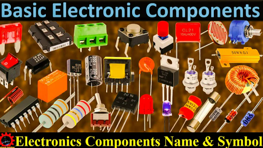
How should I learn electronic component symbols?

How should I learn electronic component symbols?

To learn electronic component symbols, you need to master basic knowledge, learn symbol rules, read relevant textbooks and materials, practice drawing and identifying circuit diagrams, refer to actual circuits, attend training classes or courses, do more practice questions and simulation tests, and interact with other learners Communication, focusing on practice and application, and constantly updating and learning new knowledge.

How should I learn electronic component symbols?

Through these methods, the understanding and mastery of electronic component symbols can be gradually improved.

Learning the symbols of electronic components requires a certain amount of time and patience. Here are some learning suggestions and detailed introductions:

Learn the basics

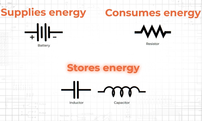
Before starting to learn electronic component symbols, it is recommended to understand some basic knowledge. For example, understand the basic components of a circuit, such as power supplies, resistors, capacitors, inductors, etc., and their roles in the circuit.

In addition, you also need to understand the classification and naming rules of electronic components in order to better understand the different types of electronic component symbols.

Learn electronic component symbols

Electronic Components Symbols and Abbreviation

When learning electronic component symbols, you can start with the most basic and common symbols. For example, learn the symbol of a resistor, the symbol of a capacitor, the symbol of an inductor, etc. While learning symbols, you also need to understand the characteristics and parameters of the electronic components represented by each symbol in order to better understand the annotations and meanings in the circuit diagram.

Learn electronic component symbols

Read relevant textbooks and information

In order to better learn electronic component symbols, you can read relevant textbooks and information. For example, you can read textbooks such as basics of circuits and basics of electronic technology. These textbooks usually introduce the symbols and characteristics of electronic components in detail. In addition, you can also refer to the data sheets and specifications of some electronic components, which will provide more detailed information and parameters.
Practice drawing and identifying circuit diagrams

Practicing drawing and identifying circuit diagrams is an important step in learning electronic component symbols. By practicing drawing circuit diagrams, you can deepen your understanding and memory of electronic component symbols. At the same time, you can also practice identifying circuit diagrams to improve your understanding and identification of electronic component symbols. When practicing drawing and identifying circuit diagrams, it is recommended to start with simple circuits and gradually transition to complex circuits to gradually improve your drawing and identification abilities.

Refer to the actual circuit

When learning electronic component symbols, you can refer to the symbols and annotations in the actual circuit for better understanding and learning. For example, you can disassemble some simple electronic devices, such as radios, remote controls, etc., observe the symbols and labels of electronic components on the circuit board, and combine them with theoretical knowledge to deepen your understanding and memory.

Attend a training class or course

In order to learn electronic component symbols more systematically, you can attend some training classes or courses. These trainings or courses usually cover basic knowledge of electronic components, symbol recognition, circuit analysis, etc., which can help learners better master the relevant knowledge of electronic component symbols.

Do more practice questions and mock tests

In order to test your learning results, you can do more practice questions and mock tests. These exercises and simulation test papers can help learners deepen their understanding and memory of electronic component symbols, and can also help learners discover their own shortcomings so that they can conduct better targeted learning.

Communicate with other learners

Networking with other learners is also a great way to learn electronic component symbols. You can communicate with other learners by joining learning groups, participating in learning forums, etc., share learning insights and experiences, and jointly improve your learning level. At the same time, you can also discover your own shortcomings through communication with other learners and learn more knowledge and skills from other learners.

Focus on practice and application

The ultimate goal of learning electronic component symbols is to apply them to actual circuits. Therefore, it is recommended that learners focus on practice and application, and deepen their understanding and memory of electronic component symbols through practical operations. For example, you can practice the connections and functions of electronic components by building actual circuits, so as to better understand the annotations and meanings in circuit diagrams.

Constantly update and learn new knowledge

Electronic technology is a field that is constantly developing and updating, and new electronic components and symbol standards are constantly emerging. Therefore, learners need to constantly update and learn new knowledge to maintain their competitiveness.

You can learn about the latest electronic component symbols and technology trends by reading relevant journals and attending technical seminars. At the same time, it is also necessary to maintain enthusiasm and continuity in learning, and continue to learn and explore new areas of knowledge.

Component manufacturers explain the difference between capacitors and inductors

Component manufacturers explain the difference between capacitors and inductors

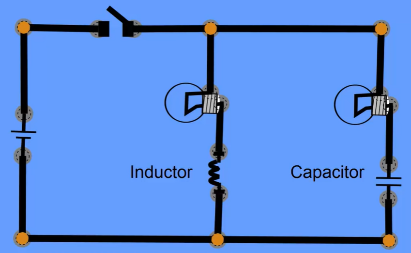
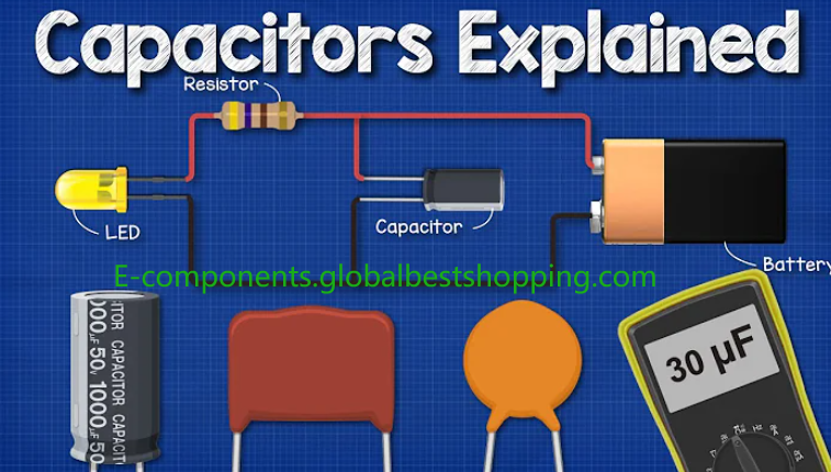
The main difference between capacitors and inductors is their working principle and purpose. Capacitors are mainly used to store electrical energy and play a role in filtering, bypassing and energy storage in circuits; while inductors store magnetic energy by establishing a magnetic field and are mainly used in AC applications such as televisions and radios.

Overview of the Differences Between Capacitors and Inductors

Capacitors and Capacitance vs Inductors and Inductance

Capacitors and inductors are two important components in electronic components. They play different roles in circuits and have unique working principles and characteristics.

As a component manufacturer, we have an in-depth understanding of the differences and characteristics of capacitors and inductors, and can provide customers with more accurate selection suggestions and technical support.

Component manufacturers explain the difference between capacitors and inductors

This article will explain the differences between capacitors and inductors in detail to help readers better understand and apply these two components.

The difference between the definitions and working principles of capacitors and inductors

  1. Capacitor: A capacitor is a component that can store electric charge. It consists of two mutually insulated conductor plates filled with dielectric in between. When a voltage is applied across the capacitor, charges accumulate on the conductor plates, forming an electric field that stores electrical energy. The capacitance of a capacitor is expressed in the unit Farad (F), which determines the capacitor’s ability to store charge.
  2. Inductor: An inductor is a component that can store magnetic energy. It is made of coils. When current flows through the inductor, a magnetic field is generated within the coil, thereby storing magnetic energy. The size of an inductor is expressed in the unit Henry (H), which determines the inductor’s ability to store magnetic energy.

Analysis of the differences between capacitors and inductors

Experts explain Capacitors and Inductors
  1. Working principle: Capacitors store electrical energy by storing electric charge, while inductors store energy by storing magnetic energy. These two energy storage methods have different physical properties and application scenarios.
  2. Frequency response: Capacitors are more sensitive to high-frequency signals, while inductors are more sensitive to low-frequency signals. This is because capacitors have less impedance at high frequencies, while inductors have greater impedance at low frequencies.
  3. Impedance characteristics: The impedance of a capacitor is inversely proportional to frequency, while the impedance of an inductor is directly proportional to frequency. This means that at low frequencies, the impedance of the capacitor is larger and the impedance of the inductor is smaller; at high frequencies, the opposite is true.
  4. Charge and discharge characteristics: Capacitors have fast charge and discharge characteristics, while the charge and discharge process of inductors is relatively slow. This makes capacitors more suitable for applications that require fast response, such as filtering, coupling, etc.; while inductors are suitable for applications that require smooth current or energy storage.
  5. Application fields: Since capacitors and inductors have different working principles and characteristics, their application fields in practical applications are also different. Capacitors are widely used in power supply filtering, signal coupling, oscillation circuits and other fields; while inductors are often used in power supply filtering, power factor correction, transformers and other fields.

Capacitor and inductor selection and application recommendations

Capacitor and inductor selection and application recommendations
  1. Selection suggestions: When selecting capacitors or inductors, comprehensive considerations need to be made based on the actual circuit requirements and performance indicators. For example, where fast charge and discharge are required, capacitors with low internal resistance and high charge and discharge speed should be selected; where smooth current is required, inductors with larger inductance and lower DC resistance should be selected.
  2. Application suggestions: In practical applications, the combined use of capacitors and inductors can achieve optimal circuit design. For example, in a power supply filter circuit, using both a capacitor and an inductor can more effectively filter out high-frequency noise and ripple in the power supply; in an oscillation circuit, oscillation signals of different frequencies can be achieved by adjusting the parameters of the capacitor and inductor. output.

Conclusion on the difference between capacitors and inductors

Through the detailed explanation of this article, we can clearly see the significant differences between capacitors and inductors in terms of working principles, frequency response, impedance characteristics, charge and discharge characteristics, and application fields.

As a component manufacturer, we hope to help engineers better understand and apply these two important electronic components by providing accurate technical information and selection suggestions.

In the future technological development, we will continue to pay attention to the research progress and application innovation of capacitors and inductors, and provide customers with better products and services.

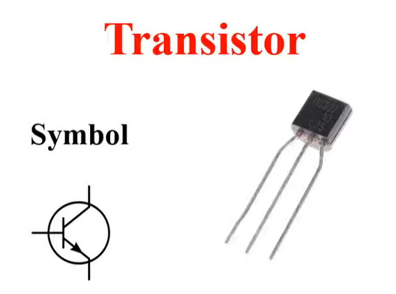
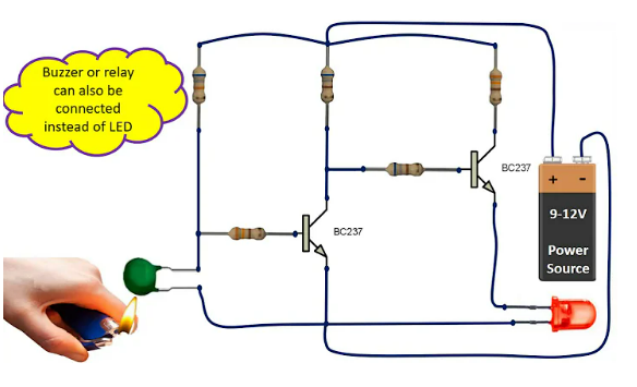
NPN Transistor Fabrication Steps and Chemical Analysis

NPN transistor fabrication steps and chemical analysis

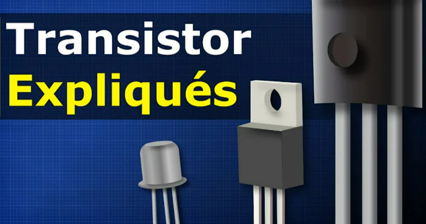
NPN transistors are three-terminal semiconductor devices consisting of a base, an emitter, and a collector. It is one of the most important components in electronic circuits and is used for amplification, switching and logic operations.

The manufacturing process of NPN transistors is divided into the following steps:

Substrate selection

NPN transistor fabrication steps and chemical analysis
  1. Select the appropriate substrate material, such as silicon wafer, germanium wafer, etc., according to the specifications and application requirements of the transistor.
  2. Consider the mechanical properties, thermal stability, chemical stability and compatibility with subsequent processes of the substrate.

surface treatment

  1. Clean the substrate to remove surface impurities and contaminants.
  2. Carry out oxidation or nitriding treatment to form a protective layer and improve surface properties.

crystal growth

From sand to silicon – transistor crystal growth process – transistor chemistry research and analysis
  1. Use physical vapor deposition, chemical vapor deposition and other methods to grow single crystal materials on the selected substrate.
  2. Control parameters such as temperature, pressure, air flow, etc. to ensure the quality and stability of crystal growth.

transistor doping

  1. The required impurities are introduced into the crystal by methods such as ion implantation, diffusion or chemical vapor deposition.
  2. The purpose of doping is to form a conductive channel and control the conductive performance of the transistor.

Transistors make PN junctions

NPN transistor fabrication steps and chemical analysis
  1. Perform photolithography, etching and other processes on the crystal surface to form a PN junction structure.
  2. The PN junction is formed through heat treatment or chemical treatment.

Transistor electrode manufacturing

How to make electrodes for transistors – Electronics: NPN Transistors
  1. Make metal electrodes on the crystal surface to realize current input and output.
  2. Select appropriate metal materials and process conditions to ensure good contact between the electrode and the crystal material.

Transistor packaging testing

  1. Encapsulate the transistor in a suitable casing to protect it from the external environment.
  2. Conduct electrical performance testing to ensure the normal function and stable performance of the transistor.

Chemical analysis of NPN transistors

Ingredient analysis

  1. Determine the types and contents of various elements in the crystal through mass spectrometer (MS) or X-ray fluorescence spectrometer (XRF).
  2. Determine the distribution and concentration of impurity elements and evaluate their impact on transistor performance.

Chemical bonding state analysis

Transistor expert explains circuit analysis of transistor (NPN and PNP) circuits
  1. Use infrared spectroscopy (IR) technology to analyze the chemical bonding state in the crystal.
  2. Understand the role of different chemical bonds in crystals and their impact on transistor performance.

Surface chemical analysis

  1. Use techniques such as atomic force microscopy (AFM) and X-ray photoelectron spectroscopy (XPS) to analyze the chemical properties and element distribution on the crystal surface.
  2. Understand the presence of surface contaminants and their impact on transistor performance.

Chemical stability analysis

  1. Evaluate the stability of crystals under different temperatures and atmospheres through thermogravimetric analysis (TGA), differential thermal analysis (DSC) and other methods.
  2. Analyze the performance changes of crystals in harsh environments to provide basis for their application.
Transistor example

Comprehensive analysis methods combined with computer simulation technology

Build more accurate models to predict and optimize transistor performance.

transistors for computers - transistors symbol

Through the above introduction of manufacturing steps and chemical analysis, we can better understand the manufacturing process and performance characteristics of NPN transistors, and provide guidance for actual production and application.

Chemical analysis of NPN transistors can be used to determine their structure and composition. Commonly used analysis methods include:

Energy spectroscopy

Energy spectroscopy can be used to determine the content of elements in a transistor.

Spectroscopy

Spectroscopy can be used to determine the type and concentration of impurities in a transistor.

Electrochemical analysis

Electrochemical analysis can be used to determine the doping type and concentration of a transistor.

These analytical methods help manufacturers ensure that transistors meet required characteristics.

What instruments and equipment are needed for chemical analysis of NPN transistors?

Transistor Manufacturer Brand - Infineon

When performing chemical analysis of NPN transistors, you may need to use the following instruments and equipment:

electron microscope

Used to observe the microstructure of the crystal surface and interior.

X-ray diffractometer

It is used to determine the crystal structure and analyze the atomic spacing and relative content of various elements in the crystal.

infrared spectrometer

Used to determine chemical bonds and molecular structure in crystals.

atomic force microscope

Used to analyze the morphology and chemical properties of crystal surfaces.

mass spectrometer

Used to determine the relative content of elements in crystals.

Electronic energy spectrometer

Used to analyze the chemical state and electronic structure of crystal surface elements.

These instruments can help us deeply understand the chemical and physical properties of NPN transistors, thereby optimizing their performance and improving their reliability.

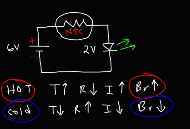
LED flash substrate temperature detection based on NTC thermistor

LED flash substrate temperature detection based on NTC thermistor

NTC thermistor-based LED flash substrate temperature detection is a method that uses NTC thermistors to monitor the temperature of the LED flash substrate in real time to ensure that the LED flash operates within the normal temperature range.

LED flash substrate temperature detection based on NTC thermistor

When the substrate temperature exceeds the set threshold, the system triggers an alarm or takes other cooling measures, thereby extending the life of the LED flash and improving its reliability.

This temperature detection method has wide application value in photography, stage lighting and other fields.

Introduction

With the continuous development of electronic technology, LED flash substrates are increasingly used in various electronic devices. However, the LED flash substrate generates a large amount of heat during operation. If the heat is not properly controlled, it may affect the performance and life of the substrate. Therefore, it is particularly important to detect and control the temperature of the LED flash substrate in real time. This article will introduce a LED flash substrate temperature detection method based on NTC thermistor.

LED flash substrate temperature detection principle based on NTC thermistor

Introduction to NTC thermistor

NTC (Negative Temperature Coefficient) thermistor is a semiconductor material with a negative temperature coefficient, and its resistance decreases as the temperature increases. Due to its unique temperature characteristics, NTC thermistors are widely used in temperature measurement and control fields. In the temperature detection of LED flash substrate, NTC thermistor can be used as a temperature sensor to monitor the temperature changes of the substrate in real time.

LED flash substrate temperature detection principle based on NTC thermistor

The principle of LED flash substrate temperature detection based on NTC thermistor is as follows:

  1. Install an NTC thermistor on the LED flash substrate, connect one end of it to the power supply, and the other end to a measuring device such as a digital multimeter or microprocessor.
  2. When the LED flash substrate generates heat, the resistance value of the NTC thermistor will change. Since there is a certain relationship between resistance and temperature, the temperature of the substrate can be measured indirectly by measuring the resistance of the NTC thermistor.
  3. Read the resistance value of the NTC thermistor through a measuring device such as a digital multimeter or microprocessor and convert it into the corresponding temperature value. In this way, the temperature changes of the LED flash substrate can be monitored in real time.

LED flash substrate temperature detection method based on NTC thermistor

The LED flash substrate temperature detection method based on NTC thermistor is as follows:

  1. Select the appropriate NTC thermistor model and specification, and select the appropriate resistance range and accuracy level according to actual needs.
  2. Install the NTC thermistor at an appropriate position on the LED flash substrate to ensure that it can accurately reflect the temperature changes of the substrate.
  3. Read the resistance value of the NTC thermistor through a measuring device such as a digital multimeter or microprocessor and convert it into the corresponding temperature value.
  4. Set the temperature threshold according to actual needs. When the substrate temperature exceeds the threshold, take corresponding control measures, such as reducing current, increasing heat dissipation, etc., to ensure the stability and reliability of the substrate.
  5. Calibrate and maintain the NTC thermistor regularly to ensure its accuracy and reliability.

Advantages of LED flash substrate temperature detection based on NTC thermistor

LED flash substrate temperature detection based on NTC thermistor has the following advantages:

  1. Real-time: NTC thermistor can monitor the temperature changes of the LED flash substrate in real time, providing timely information support for control measures.
  2. High accuracy: NTC thermistor has high resistance value accuracy and temperature resolution, and can accurately reflect the temperature changes of the substrate.
  3. Good stability: NTC thermistor has stable temperature characteristics and can maintain good performance in a wide temperature range.
  4. Low cost: Compared with other temperature sensors, NTC thermistors have lower cost and smaller size, and are suitable for various miniaturized electronic devices.
  5. Easy to maintain: NTC thermistor has a simple structure, is easy to install and maintain, and can meet the needs of various practical applications.

Summarize

LED flash substrate temperature detection based on NTC thermistor is an effective temperature detection method with the advantages of real-time performance, high accuracy, good stability, low cost and easy maintenance. In practical applications, appropriate NTC thermistor models and specifications can be selected according to specific needs, and corresponding control measures can be taken to ensure the stability and reliability of the LED flash substrate.

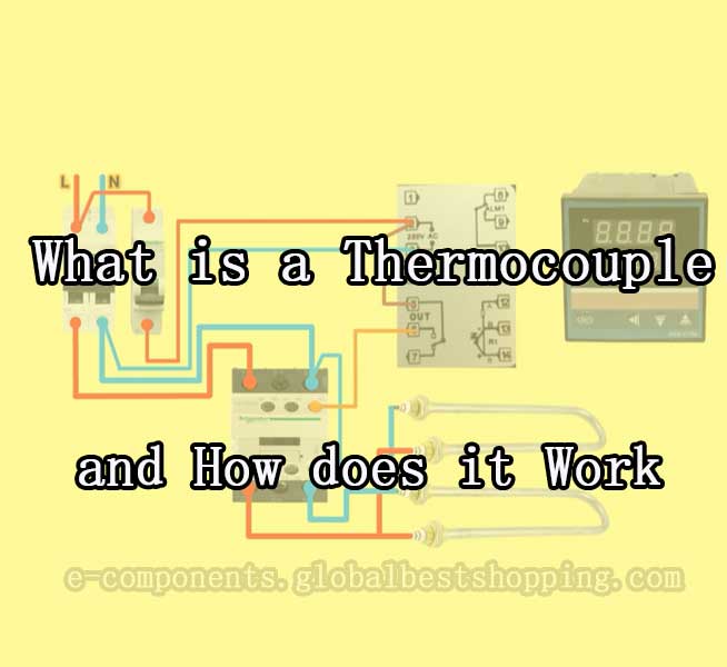
What is a Thermocouple and how does it work

working principle of thermocouple with diagram

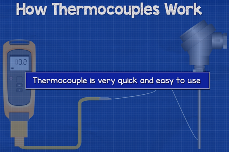
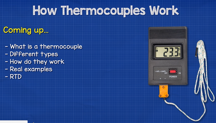
A thermocouple is a temperature measuring element that can directly measure temperature and convert the temperature signal into a thermoelectromotive force signal, which is then converted into the temperature of the measured medium through an electrical instrument (secondary instrument).

The shapes of various thermocouples are often very different due to needs, but the basic structure is roughly the same. They usually consist of main parts such as hot electrodes, insulating sleeves, protective tubes, and junction boxes. They are usually matched with display instruments, recording instruments, and electronic regulators. use.

What is a Thermocouple and how does it work

Are thermocouples electronic components?

Thermocouples are electronic components. It is composed of two probes made of different metals or alloys. When the two ends of the probe come into contact with objects with different temperatures, an electromotive force is generated.

The magnitude of the electromotive force is proportional to the temperature difference of the probe. Therefore, thermocouples can be used to measure temperature.

Are thermocouples electronic components or electronic devices?

Thermocouples are both electronic components and electronic devices.

From the perspective of electronic components, a thermocouple is composed of two probes made of different metals or alloys. When the two ends of the probes come into contact with objects with different temperatures, an electromotive force is generated. The magnitude of the electromotive force is proportional to the temperature difference of the probe. Therefore, thermocouples can be used to measure temperature.

From an electronics perspective, thermocouples often form temperature detectors along with other circuit components. The temperature detector can convert the electromotive force generated by the thermocouple into a digital signal and output the digital signal to the control circuit. Control circuits can control the operation of equipment based on digital signals.

Therefore, thermocouples are electronic components that can be used alone or together with other circuit components to form electronic devices.
Thermocouple is a very important electronic component with a wide range of applications.

How do thermocouples work?

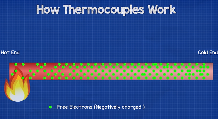
The working principle of thermocouples is the thermoelectric effect. Specifically, two wires of different metals are connected to form a circuit, one of the contacts is heated, and the other contact is in an unheated (cold spot) state.

How do thermocouples work?

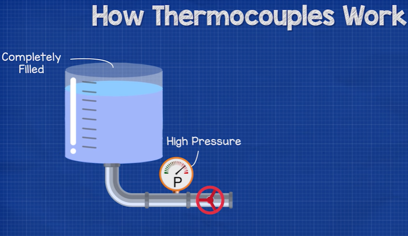
Due to the different electron concentrations and movement speeds in different metals, a The phenomenon of electron diffusion forms a current in a closed circuit, producing a wide temperature difference electromotive force.

working principle of thermocouple with diagram

This electromotive force is called thermoelectric potential. By measuring the magnitude of the thermoelectric potential, the temperature of the measured point can be known.

What are the disadvantages of thermocouples?

As a common temperature sensor, thermocouples have many advantages, such as wide temperature measurement range, stable performance, high measurement accuracy, fast thermal response time, high mechanical strength, high temperature resistance, long service life, etc. However, it also has some disadvantages, including:

  1. Low accuracy: The accuracy of thermocouples is usually affected by a variety of factors, such as internal inherent inaccuracies caused by metal properties, errors in the signal scheduling process, etc., resulting in low accuracy.
  2. Susceptible to corrosion: Since the thermocouple is composed of two different metals, corrosion over time may affect accuracy under some working conditions. Therefore, they may require protection, and maintenance and protection is essential.
  3. Poor noise immunity: Noise generated by stray electric and magnetic fields can cause problems when measuring millivolt-level signal changes. Twisted thermocouple wire pairs may significantly reduce magnetic field coupling. Electric field coupling can be reduced by using shielded cables or routing and shielding within metal conduits. The measurement component should provide signal filtering in the form of hardware or software to effectively suppress power frequency (50 Hz/60 Hz) and its harmonics.

Despite these shortcomings, thermocouples are still widely used in many fields.

What are the application areas of thermocouples?

What are the application areas of thermocouples?

The application fields of thermocouples are very wide, including but not limited to the following aspects:

Power metallurgy

Used to measure and control temperature parameters in various production processes, such as heating processes, smelting processes, etc.

Petrochemical industry

In the petrochemical industry, thermocouples are used to measure and control the temperature of various chemical reactions to ensure the stability and safety of the production process.

Food processing

During food processing, thermocouples can be used to measure and control the temperature of food processing equipment to ensure food hygiene and quality.

Water treatment

During the water treatment process, thermocouples can be used to measure and control the temperature of water treatment equipment to ensure the efficiency and effectiveness of water treatment.

Thermocouple is a temperature measurement element widely used in various industrial fields and plays an important role in ensuring the stability and safety of the production process.

What are the characteristics and uses of Thermocouples?

Thermocouple temperature measuring elements have the following characteristics and uses:

High measurement accuracy

Thermocouples have high measurement accuracy and can meet the temperature measurement needs in various industrial production processes.

Wide measurement range

Thermocouples have a wide measurement range, ranging from low temperature to high temperature, and are suitable for various industrial fields.

Fast response speed

The thermocouple has a fast response speed and can quickly respond to temperature changes and transmit temperature data in a timely manner.

Simple structure

The thermocouple has a simple structure, is easy to install and maintain, and can adapt to various harsh environments.

Strong corrosion resistance

Thermocouples have strong corrosion resistance and can adapt to various chemical substances and high temperature environments to ensure measurement accuracy and stability.

Affordable price

Thermocouples are affordable, cost-effective, and suitable for large-scale applications.

In the field of industrial automation, thermocouples are mainly used for temperature measurement and control.

It can be installed on various industrial equipment, such as boilers, steam turbines, reactors, etc., to monitor the operating temperature of the equipment in real time and transmit the data to the control system to help operators adjust operating parameters in a timely manner to ensure normal operation of the equipment.

At the same time, thermocouples can also be used for temperature compensation and parameter adjustment of control systems to improve production efficiency and product quality.

What role do thermocouples play in industrial automation?

In the field of industrial automation, the main role of thermocouples is to measure and control temperature.

A thermocouple is a sensor that directly measures temperature. It can convert the temperature into an electrical signal, and then convert it into the temperature of the measured medium through an electrical instrument (secondary instrument). Therefore, thermocouples are key components for automatic temperature control.

What role do thermocouples play in industrial automation?

In many industrial production processes, such as steel smelting, chemical reactions, glass manufacturing, etc., precise temperature control is required. In these cases, thermocouples can measure temperature in real time and transmit the data to the control system to help operators adjust operating parameters in a timely manner to ensure normal operation of equipment and improve production efficiency and product quality.

At the same time, thermocouples are also widely used in the power industry. In the power industry, the operating temperature of boilers, turbines and other equipment is critical to power production. Thermocouples can monitor the operating temperature of the equipment in real time and transmit the data to the control system to help operators adjust operating parameters in a timely manner to ensure normal operation of the equipment.

In addition, thermocouples also have the advantages of simple structure, easy use, and stable performance, so they have been widely used in the field of industrial automation.

Thermocouple Example

How does a thermocouple work on a gas valve

The basic principle of thermocouples working on gas valves is to utilize the thermoelectric effect. The thermoelectric effect refers to the phenomenon that an electromotive force is generated when the electrodes of two different conductors or semiconductors come into contact with objects of different temperatures.

On gas valves, thermocouples are usually used to detect the temperature of gas after combustion. The two probes of the thermocouple are in contact with the air after gas combustion and the external air respectively. When the gas is burned, the temperature of the air will increase. Because the two probes of the thermocouple have different temperatures, an electromotive force is generated. The magnitude of the electromotive force is proportional to the temperature difference between the two probes.

The control circuit of the gas valve controls the flow of gas based on the electromotive force generated by the thermocouple. When the air temperature after gas combustion reaches a certain value, the control circuit will cut off the flow of gas. This can prevent excessive combustion of gas and cause safety accidents.

Specifically, the working process of thermocouples on gas valves is as follows:

  1. Contact the two probes of the thermocouple with the air after gas combustion and the external air respectively.
  2. When gas is burned, the temperature of the air will increase.
  3. Since the two probes of the thermocouple have different temperatures, an electromotive force will be generated.
  4. The magnitude of the electromotive force is proportional to the temperature difference between the two probes.
  5. The control circuit of the gas valve will control the flow of gas based on the electromotive force generated by the thermocouple.

A thermocouple is a very effective gas valve temperature detector. It has the following advantages:

  • High precision. The measurement accuracy of thermocouples can reach ±0.1°C.
  • Good stability. The measurement stability of the thermocouple can reach ±0.01℃.
  • Good durability. The service life of thermocouples can reach more than 50,000 hours.

Therefore, thermocouples are widely used in gas valves.

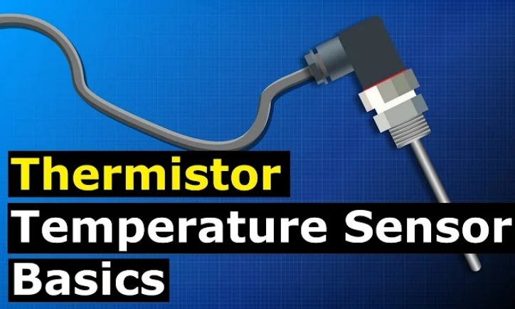
Research and analysis on the working principle of Thermistor

Research and analysis on the working principle of thermistor

What is a Thermistor?

A thermistor is a sensor resistor whose resistance changes as temperature changes. The working principle of the thermistor is to use a sensor to help adjust the temperature.

What is a thermistor?

Its functions include voltage adjustment, volume control, time delay and circuit protection.

The thermistor has the functions of temperature measurement, temperature compensation, overheating protection, and liquid level measurement.

Research and analysis on the working principle of thermistor

What are heat-sensitive materials?

Thermosensitive material is a material that can sense temperature changes, and its physical properties such as resistance, capacitance, and inductance will change with changes in temperature. This material is usually composed of heat-sensitive materials and insulating materials. The heat-sensitive materials can sense temperature changes and generate corresponding electrical signals, while the insulating materials can ensure the stable transmission of electrical signals.

Is the thermistor an electronic component? What are heat-sensitive materials?

Thermosensitive materials are widely used in many fields, such as temperature measurement, control, circuit protection, sound control, etc. For example, in temperature measurement and control, thermistors can be used to measure changes in temperature and convert the temperature signal into an electrical signal to achieve precise control of temperature.

In short, a thermosensitive material is a material that can sense temperature changes and generate corresponding electrical signals. It has wide applications in many fields.

Is the thermistor an electronic component?

Thermistors are electronic components. It is a resistor that changes with temperature, made by using the resistance of heat-sensitive materials to change with temperature.

How does a thermistor work?

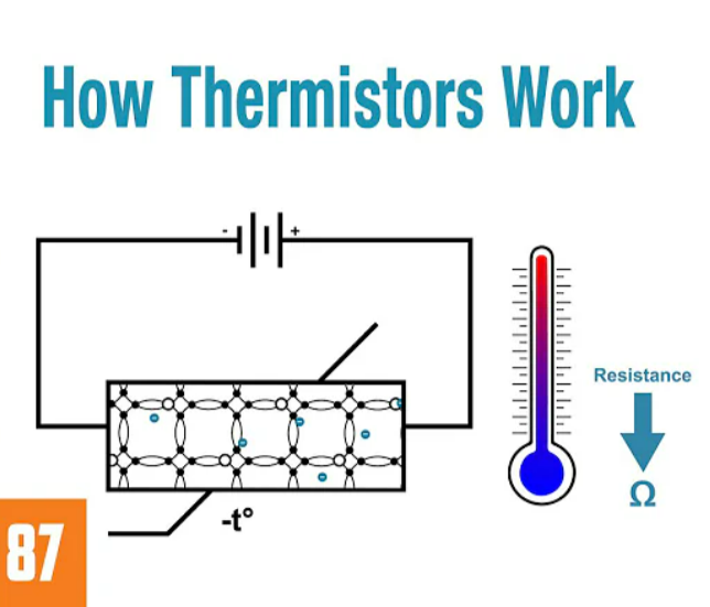
The working principle of the thermistor is to utilize the heat-sensitive effect of the semiconductor. When the temperature changes, the resistance value of the semiconductor will change, thereby achieving the measurement of temperature.

How does a thermistor work?

Specifically, when the temperature rises, the carrier concentration of the semiconductor increases and the resistivity decreases, causing the resistance of the thermistor to decrease; conversely, when the temperature decreases, the carrier concentration of the semiconductor decreases and the resistivity increases, causing the resistance of the thermistor to increase. By measuring the change in resistance of the thermistor, the change in temperature can be deduced.

The types and characteristics of thermistors vary depending on materials and structures, and the appropriate type and specifications need to be selected based on actual application requirements. It has been widely used in temperature measurement, temperature control, medical equipment, automotive electronics, aerospace and other fields. In practical applications, it is necessary to pay attention to the thermistor’s stability, linearity, response time and other performance indicators to ensure its measurement and control accuracy.

In addition, thermistors can also be used to implement functions such as circuit protection and volume control. For example, in audio amplifiers, thermistors can be used to adjust the volume; in circuit protection, when the current in the circuit is too large, the thermistors can automatically cut off the circuit to protect the circuit from damage.

how does a negative temperature coefficient thermistor work

The thermistor is a sensor made by utilizing the heat-sensitive effect of semiconductors. It has the advantages of high measurement accuracy, fast response speed, simple structure, and affordable price. In actual applications, it is necessary to select the appropriate type and specification according to actual needs, and pay attention to its stability, linearity, response time and other performance indicators.

The main differences between thermocouples and thermistors

The main differences between thermocouples and thermistors are reflected in the following aspects:

  1. Working principle: The working principle of a thermocouple is to use the potential difference between electrodes of two different materials to generate an electric potential related to temperature, which is called thermoelectromotive force. The thermistor uses the different resistance values of different temperatures to directly convert changes in temperature into changes in electricity.
  2. Signal properties: The thermistor itself is a resistor, and the resistance changes with changes in temperature. The thermocouple generates different induced voltages with different temperatures.
  3. Measuring range: The measuring range of the thermistor is generally between -50°C and +300°C, while the measuring range of the thermocouple can reach over 2000°C.
  4. Advantages and Disadvantages: The advantages of the thermistor are high precision and fast response speed, but its disadvantage is low sensitivity and the need for external circuit amplification. The advantages of thermocouples are high sensitivity and fast response, but their disadvantage is relatively low accuracy.

To sum up, the main differences between thermocouples and thermistors lie in their working principles, signal properties, measurement ranges, and advantages and disadvantages. In practical applications, selection needs to be based on specific measurement requirements.

Research and analysis on the working principle of thermistor

Introduction

The thermistor is an electronic component widely used in the field of temperature measurement and control. It has the advantages of high measurement accuracy, fast response speed, simple structure, and affordable price, so it has been widely used in various industrial fields. This article will conduct a detailed research and analysis on the working principle of the thermistor, aiming to gain an in-depth understanding of its working principle and performance characteristics and provide theoretical support for practical applications.

Basic principles of thermistor

The thermistor is a sensor made using the heat-sensitive effect of semiconductors. When the temperature changes, the resistance value of the semiconductor changes, allowing the temperature to be measured. The basic principles of thermistors can be summarized in the following steps:

  1. Temperature changes cause changes in carrier concentration inside semiconductor materials.
  2. Changes in carrier concentration cause changes in the resistivity of semiconductor materials.
  3. Changes in resistivity cause changes in the resistance of the thermistor.
  4. By measuring the resistance change of the thermistor, the temperature change can be calculated.

Types and characteristics of thermistors

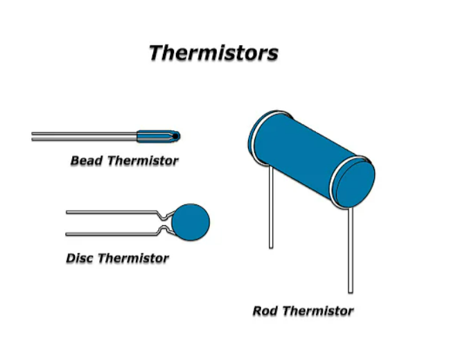
  1. Type: Thermistors can be divided into metal thermistors, ceramic thermistors and semiconductor thermistors according to different materials and structures. Among them, the advantages of metal thermistors are good stability, high precision, and fast response speed, but the disadvantage is that the measurement range is narrow; the advantages of ceramic thermistors are high temperature resistance and corrosion resistance, but the disadvantage is poor stability; semiconductors The advantages of the thermistor are high sensitivity, good stability and fast response speed, but the disadvantage is that the measurement range is narrow.
  2. Characteristics: The main characteristics of the thermistor include temperature coefficient, sensitivity, linearity, stability and response time. Among them, the temperature coefficient refers to the percentage change in resistance value caused by a unit temperature change; sensitivity refers to the change in resistance value when the temperature changes by a certain amount; linearity refers to the linear relationship between temperature and resistance value; stability refers to resistance The stability of the value over time; response time is the time it takes for a temperature change to cause a change in resistance value.

Application fields of thermistor

  1. Temperature measurement: Thermistors can be used in various temperature measurement devices, such as thermometers, temperature sensors, etc., to achieve accurate measurement and control of temperature.
  2. Temperature control: In the industrial production process, precise control of temperature is required. Thermistors can be used in various temperature control equipment, such as heaters, refrigerators, etc., to achieve precise control and regulation of temperature.
  3. Medical equipment: In the medical field, the patient’s body temperature needs to be accurately measured. Thermistors can be used in various medical equipment, such as thermometers, monitors, etc., to achieve accurate measurement and monitoring of patient body temperature.
  4. Automotive electronics: In the automotive field, the temperature of the engine needs to be precisely controlled. Thermistors can be used in various automotive electronic equipment, such as engine controllers, air conditioning controllers, etc., to achieve precise control and regulation of engine temperature.
  5. Aerospace: In the aerospace field, the temperature of the aircraft needs to be precisely controlled. Thermistors can be used in various aerospace equipment, such as aircraft controllers, navigation systems, etc., to achieve precise control and regulation of aircraft temperature.

Conclusion

Through research and analysis of the working principle and performance characteristics of the thermistor, we can draw the following conclusions:

  1. The thermistor is a sensor made by utilizing the heat-sensitive effect of semiconductors. It has the advantages of high measurement accuracy, fast response speed, simple structure, and affordable price.
  2. The types and characteristics of thermistors vary depending on materials and structures, and the appropriate type and specifications need to be selected according to actual application requirements.
  3. Thermistors are widely used in temperature measurement, temperature control, medical equipment, automotive electronics, aerospace and other fields.
  4. In practical applications, it is necessary to pay attention to the thermistor’s stability, linearity, response time and other performance indicators to ensure its measurement and control accuracy.

What is KS3307DD?

What is KS3307DD?

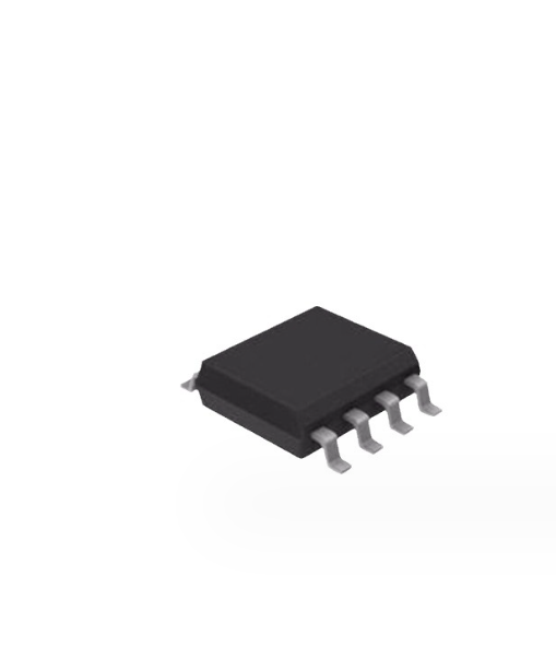
KS3307DD is an electronic component model. The KS3307DD is a 1.5A step-down switching power supply controller manufactured by ON Semiconductor.

It comes in a 4-pin package and has the following features:

  • Input voltage range: 3.3V to 36V
  • Output voltage range: 0.8V to 36V
  • Maximum output current: 1.5A
  • Working frequency: 1.2MHz
  • Efficiency: more than 90%

KS3307DD datasheet

parametervalue
modelKS3307DD
manufacturerON Semiconductor
encapsulationSOIC-8
Pinout1. VDD 2. IN 3. GND 4. OUT
Input voltage range3.3V to 36V
Output voltage range0.8V to 36V
Maximum output current1.5A
working frequency1.2MHz
efficiencyMore than 90%
Starting current60mA
Quiescent Current1.5uA
size2.0 x 1.25 mm
  • Input voltage range: The input voltage range of KS3307DD is 3.3V to 36V. This means it can be powered from a variety of power sources, including batteries, AC power, and DC power.
  • Output voltage range: The output voltage range of KS3307DD is 0.8V to 36V. This means it can power a variety of electronic devices, including microcontrollers, digital circuits, and analog circuits.
  • Maximum output current: The maximum output current of KS3307DD is 1.5A. This means it can power more powerful electronic devices.
  • Operating frequency: The operating frequency of KS3307DD is 1.2MHz. This means it can achieve high efficiency.
  • Efficiency: The KS3307DD has an efficiency of over 90%. This means that it can convert most of the input power into output power, thereby reducing waste of power.
  • Start-up current: The start-up current of KS3307DD is 60mA. This means it can boot from a low power source.
  • Quiescent current: The quiescent current of KS3307DD is 1.5uA. This means it consumes very little power when idle.
  • Dimensions: The KS3307DD measures 2.0 x 1.25 mm. This means it can be used in small electronic devices.

Application fields of step-down switching power supply controller KS3307DD

KS3307DD is commonly used in portable electronic devices such as laptops, tablets, and smartphones. It can also be used in industrial applications such as motor drives and lighting controls.

What is KS3307DD?

Main applications of KS3307DD include:

  • Chargers for laptops and tablets
  • Charger for smartphone
  • motor driver
  • Lighting controller
  • Battery management system
  • Solar panel system

The advantages of the step-down switching power supply controller KS3307DD include:

  • high efficiency
  • low noise
  • Wide input voltage range
  • Small size
  • low cost

The disadvantages of the step-down switching power supply controller KS3307DD include:

  • Requires external inductor and diode
  • Requires external regulator

All in all, the KS3307DD is a powerful step-down switching power supply controller with a wide range of applications.

KS3307DD component manufacturer introduction - ON Semiconductor

KS3307DD component manufacturer introduction

The KS3307DD capacitive component is manufactured by ON Semiconductor. ON Semiconductor is an American company headquartered in San Jose, California. It is a leading global semiconductor company, offering a broad range of products including power semiconductors, sensors, logic, mixed-signal and analog products.

Frequently asked questions about KS3307DD capacitor components

Frequently asked questions about KS3307DD capacitor components

What component is KS3307DD?

KS3307DD is a capacitor component.

Which country is the KS3307DD capacitor component manufacturer from?

The manufacturer of KS3307DD capacitor components is American.

What is the packaging form of KS3307DD?

The KS3307DD is available in a 4-pin package measuring 2.0 x 1.25 mm. The package form is SOIC-8.

What is the difference between capacitor and inductor

what is the difference between capacitor and inductor

Capacitors and inductors are both commonly used energy storage components in electronic circuits, but they have obvious differences in structure, principle, characteristics and applications.

structure

A capacitor consists of two conductive plates and a medium. When a voltage is applied between the two plates, charges will be distributed between the two plates, forming an electric field. An inductor is made of wire wound around it, and when the current through the wire changes, a magnetic field is created around the wire.

What is the difference between capacitor and inductor

principle

The principle of capacitance is to store energy in an electric field. When a voltage is applied between the two plates, charges will be distributed between the two plates to form an electric field. The energy of the electric field is equal to the sum of the energy of the charge and the potential energy of the electric field. The principle of inductance is magnetic field energy storage. When the current through the wire changes, a magnetic field will be generated around the wire. The energy of the magnetic field is equal to the sum of the energy of the current and the potential energy of the magnetic field.

Inductor example

characteristic

The characteristic of capacitor is capacitive reactance, which is inversely proportional to frequency and directly proportional to capacity. The characteristic of an inductor is inductive reactance, which is proportional to frequency and proportional to the inductance.

application

Capacitors mainly play roles in filtering, coupling, oscillation, and delay in circuits. The inductor mainly plays the functions of filtering, oscillation, delay, and notch in the circuit.

Specific differences

Inductor Vs. Capacitor
FeaturesCapacitorInductor
StructureConsists of two conductive plates and dielectricMade of wire
PrincipleElectric field energy storageMagnetic field energy storage
CharacteristicCapacitive reactance is inversely proportional to frequency and directly proportional to capacityInductive reactance is proportional to frequency and proportional to inductance
ApplicationFiltering, coupling, oscillation, delayFiltering, oscillation, delay, notch

All in all, capacitors and inductors are important energy storage components in electronic circuits. They have obvious differences in structure, principle, characteristics and applications.

Inductor Vs. Capacitor - Contact capacitor or inductor manufacturers and suppliers

Research and analysis on the difference between capacitance and inductance

There are significant differences between capacitors and inductors in many aspects. The following is a specific analysis:

form of stored energy

Capacitor is an energy storage component, which stores electrical energy. The inductor converts electrical energy into magnetic energy and stores it.

Response to current in a circuit

Capacitors respond quickly to current in a circuit, while inductors respond slowly to current in a circuit. This means that in an AC circuit, a capacitor will charge and discharge faster, while an inductor will delay the change in current.

Frequency response in the circuit

Capacitors respond well to high-frequency signals and poorly to low-frequency signals; while inductors respond well to low-frequency signals and poorly to high-frequency signals. This characteristic has important applications in filtering, resonance and other circuits.

Inductor vs. Capacitor Icon

Scope of use

Capacitors are mainly used to store electrical energy and adjust circuit characteristics, such as filtering, decoupling, tuning, etc.; while inductors are mainly used to limit current and adjust circuit characteristics, such as chokes, transformers, etc.

In general, capacitors and inductors are different in terms of energy storage form, current response, frequency response, and range of use. When using it, you need to select the appropriate capacitor or inductor according to the specific needs and circuit characteristics.

Do I need a product certificate to purchase electronic components through customs?

Do I need a product certificate to purchase electronic components through customs?

When purchasing electronic components to go through customs, whether a product certification certificate is required depends on many factors, including the requirements of the importing country, the type and purpose of the electronic components, and the method of import.

Do I need a product certificate to purchase electronic components through customs?

The following are some product certification certificates and related requirements that may be involved:

Importing country requirements

Different countries have different requirements for imported electronic components. Some countries may require electronic components to undergo specific certifications, such as CE certification, FCC certification, UL certification, etc., to ensure product safety and compliance with relevant regulations. Therefore, before purchasing electronic components, you need to understand the requirements of the importing country to determine whether a product certification certificate is required.

Types and uses of electronic components

Different types of electronic components may have different safety and performance requirements.

For example, some electronic components may be used in medical equipment, aerospace and other fields, which have higher requirements for product quality and safety. Therefore, for specific types of electronic components, specific product certifications may be required.

Electronic component manufacturers and suppliers

Import method

The method of importation also affects whether a product certification certificate is required. If electronic components are imported through general trade, a product certification certificate is usually required to prove the quality and safety of the product. And if electronic components are imported through special trade methods, such as donations, samples, etc., product certification certificates may not be required.

To sum up, whether a product certification certificate is required when purchasing electronic components to go through customs depends on many factors. In order to ensure smooth import and compliance with relevant regulations, it is recommended to communicate with suppliers and relevant departments of the importing country before purchasing to understand the specific requirements and procedures. At the same time, it is recommended to keep relevant product certification certificates and supporting documents so that they can be provided in time when needed.

In China, which imported electronic components do not require product certification certificates?

According to the “Announcement on No longer Implementing Compulsory Product Certification Management for Some Electronic and Electrical Products” issued by the State Administration for Market Regulation (No. 34, 2022), the compulsory product certification catalog has been adjusted to include products with low safety risks and relatively high technology. Nine mature electronic and electrical products are no longer subject to compulsory product certification management.

In China, what testing is required for imported electronic components?

Among them, there are 7 types of electronic products and safety accessories, including single and multi-speaker active speakers with a total output power of less than 500W (effective value), audio power amplifiers, and audio and video recording, playback and processing equipment in various carrier forms ( Including various types of optical disks, tapes, hard disks and other carrier forms), electronic keyboards, cordless telephone terminals, data terminals and multimedia terminals. There are 2 types of security products, including intrusion detectors and anti-theft alarm controllers.

At the same time, the majority of import traders and individuals who purchase such electronic and electrical products from abroad do not need to provide a compulsory product certification (CCC certificate) when making entry declarations to China Customs. They can directly rely on the 10-digit HS code requirements corresponding to the product. Initiate customs declaration business to the customs for other procedures.

Complete range of electronic components

Therefore, for the above nine types of electronic and electrical products, product certification certificates are not required when importing. However, please note that specific import requirements may vary depending on the importing country and import method. It is recommended to communicate with the supplier and the relevant departments of the importing country before purchasing to understand the specific requirements and procedures.

In China, what testing is required for imported electronic components?

Imported electronic components require a series of tests to ensure their quality and safety. The following are some common detection items:

Routine testing

It mainly tests the appearance, size, electrical performance, safety performance, etc. of electronic components. Test basic parameters according to the component specifications, such as triodes, including appearance, size, ICBO, VCEO, VCES, HFE, pin pull force, pin bending, solderability, soldering heat resistance and other items.

Reliability test

Mainly tests the lifespan and environmental testing of electronic components. Test the life of the device and various environmental tests according to the user’s requirements and specifications, such as high temperature test, low temperature test, moisture test, vibration test, maximum load test, high temperature durability test and other tests.

DPA analysis

It mainly controls the internal structure and process of the device. For example, transistors, the main methods include X-ray detection of the internal structure, acoustic scanning to monitor the internal structure and packaging process, and unpacking to monitor the internal wafer structure and size.

Please note that specific testing items and requirements may vary depending on the importing country and import method. Therefore, before importing electronic components, it is recommended to communicate with suppliers and relevant departments of the importing country to understand the specific requirements and procedures.