
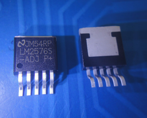
LM2576-ADJ is a monolithic step-down switching regulator produced by National Semiconductor. It is packaged in TO-220 and has only 5 pins. Its appearance is similar to that of a plastic transistor.
LM2576-ADJ is an adjustable output voltage type. Its technical parameters are: input voltage 3.5~40V, output voltage 1.23~37V, output current 3A, oscillator fixed frequency 52kHz, with TTL shutdown capability and low power standby state, and has thermal shutdown and current limiting protection functions.
What is lm2577 arduino?
LM2577 is a power module for Arduino, which is a highly efficient switching power supply controller used to convert input voltage into an adjustable output voltage. It has the advantages of high efficiency, high reliability, low noise, etc., and is suitable for various application scenarios that require high-efficiency power supply.
Arduino is an open source microcontroller development board. It has a simple and easy-to-use programming environment and rich development libraries, which can be used to quickly develop various embedded applications. By integrating the LM2577 with the Arduino development board, the input power can be converted into the required output voltage, providing a stable power supply to the Arduino.
LM2577 Arduino is a high-efficiency switching power supply controller that can be integrated with the Arduino development board and is suitable for various application scenarios that require high-efficiency power supply.
What is the input voltage range of the LM2576-ADJ?
The LM2576-ADJ has an input voltage range from 3.5V to 40V.
What is the output voltage of LM2576-ADJ?
The output voltage of LM2576-ADJ is adjustable, ranging from 1.23 to 37V.
What is the maximum output current of LM2576-ADJ?
The maximum output current of LM2576-ADJ is 3A.
Please give other technical parameters of LM2576-ADJ
Other technical parameters of LM2576-ADJ include:
- Maximum output current: 3A.
- Maximum input voltage: 40V.
- Output voltage: 3.3V, 5V, 12V, 15V and ADJ (adjustable) are optional.
- Oscillator fixed frequency: 52kHz.
- Conversion efficiency: 75% ~ 88% (efficiencies are different at different voltage outputs).
- Control mode: PWM.
- Working temperature range: -40℃~+125℃.
- Working mode: Low power consumption/normal mode can be controlled externally.
- Working mode control: TTL level compatible.
- Number of external components required: four (non-adjustable) or six (adjustable) only.
- Device protection: thermal shutdown and current limit.
- Package form: TO-220 or TO-263.
To learn more about the detailed LM2576 pin arrangement, lm2577 circuit diagram, etc., please view the Lm2576 datasheet specification pdf download.
LM2577 buck boost circuit
LM2577 is a switching power supply chip that can be used to implement a step-down DC-DC power converter. The input voltage range is 3-35V, the output voltage range is 1.25-30V, and the output current is 1A (when the input is 9-35V and the output is 12V), the output is about 5V and can reach 1.5-2A.
If you need to implement a buck-boost function, you can consider using a two-stage DC-DC power converter. The first stage steps the input voltage down to the appropriate voltage range, and the second stage boosts it to the desired output voltage.
Specific circuit design needs to consider input and output voltage, current, power and other factors, and select appropriate components and circuit topology for implementation.
lm2577 equivalent
The equivalence of electronic components refers to treating electronic components with similar characteristics and functions as the same type of devices in different circuit applications to facilitate circuit analysis and design. This equivalent treatment method is widely used in electronic technology, but in some cases there may be errors or inaccuracies.
For example, in the equivalent circuit of a reverse-conducting thyristor, the reverse-conducting thyristor is considered to be a diode connected in reverse parallel to an ordinary thyristor. This equivalent circuit can simplify the analysis and design process of reverse conduction thyristors. Similarly, other electronic components such as resistors, inductors, capacitors, etc. are often treated equivalently in circuits.
It should be noted that in some cases, electronic components of different models or characteristics may have different electrical characteristics and performance indicators, so these differences need to be taken into account in circuit analysis and design, and accurate calculations and designs must be performed.
What is the LM2576 adjustable voltage regulator?
The LM2576 adjustable regulator is a step-down switching regulator capable of driving 3A loads with excellent line and load regulation. This voltage regulator is an improved version of a switching power supply that contains all the features needed to reduce the voltage of a circuit.
The LM2576 adjustable voltage regulator is available with special load regulation and load lines, and its output voltage can be adjusted. This regulator provides excellent line and load regulation, effectively reducing vibration and oscillation within the circuit. In addition, it can perform manual shutdown and other operations through the external ON/OFF pin.
lm2577 boost circuit pcb manufacturing
The process of manufacturing the LM2577 boost circuit PCB can be carried out as follows:
- Prepare materials: including PCB sheets, copper foil, electronic components, wires, etc.
- Design circuit board: Use professional EDA (Electronic Design Automation) software, such as Altium Designer, AutoCAD, etc., to design the layout of the boost circuit PCB. When designing, factors such as the principle of the circuit, the arrangement of components, and wiring rules need to be taken into consideration to ensure the electrical performance and mechanical strength of the PCB.
- Make silk screen: Print circuit identification, component symbols and numbers and other information on the PCB board. This information will be used in subsequent welding and commissioning processes.
- SMD welding: Weld the electronic components to the PCB board according to the designed position and direction. When welding, the temperature and time need to be controlled to ensure that the solder joints are of good quality and will not cause damage to components and PCB boards.
- Testing and debugging: After completing the welding, the PCB board needs to be tested and debugged. This includes checking the electrical performance of the circuit, measuring voltage and current at key points, etc. If problems are found, appropriate adjustments and repairs need to be made.
- Assemble the casing: Place the PCB board into the casing and fix the connecting wires and other components to ensure the stability and reliability of the entire boost circuit.
- Quality inspection: Inspect appearance, size, electrical performance, etc. to ensure that the quality of the boost circuit meets the requirements.
Manufacturing the LM2577 boost circuit PCB requires professional technical and equipment support, as well as a strict quality control system to ensure product quality and reliability. If you are not familiar with the PCB manufacturing process and technology, it is recommended to seek help from a professional PCB manufacturer or electronic engineer.