Analysis of capacitor chemical element composition and working principle

Analysis of capacitor chemical element composition and working principle

The chemical element composition of the capacitor mainly includes metal electrodes and electrolytes. Metal electrodes usually use metal materials with good electrical conductivity such as aluminum and tantalum, while electrolytes choose different types of dielectric materials according to different application requirements.

The working principle of capacitors is mainly based on the storage and release of electric charge. When a voltage is applied between the two plates of the capacitor, the charge will be distributed on the two electrode plates of the capacitor, forming an electric field. When the voltage is removed, the charges are redistributed, creating a reverse electric field. This process is the charging and discharging process of the capacitor.

Chip capacitor 0603 manufacturer wholesale chip capacitor 0805 1206 high voltage capacitor electronic components

During the charging and discharging process of the capacitor, electrical energy will be converted into other forms of energy, such as thermal energy or mechanical energy. Therefore, capacitors play a role in storing and transmitting energy in circuits and are widely used in various electronic devices.

What are the chemical elements of a capacitor?

The chemical element composition of the capacitor mainly includes metal electrode materials and electrolyte materials.

  1. Metal electrode material: Metals with high conductivity are usually selected, such as aluminum, tantalum, etc. These metals are treated with special chemicals to form extremely thin metal foils, thereby increasing the surface area of the electrode and improving the energy storage density of the capacitor.
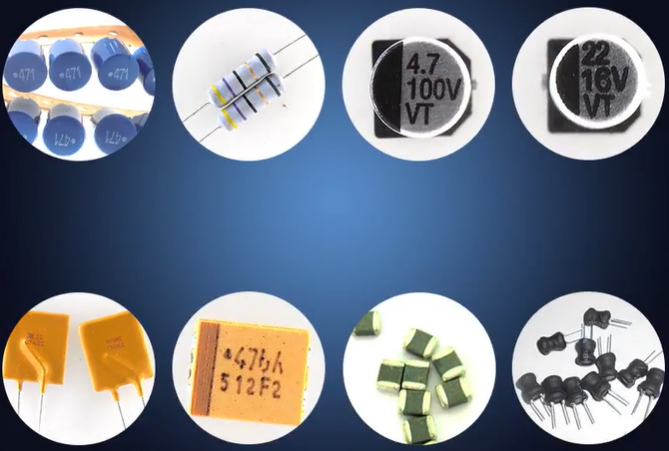
  2. Electrolyte material: This is another important component in the capacitor. Its function is to form a conductive path between the two electrodes. Depending on the type of electrolyte, capacitors can be divided into many types, such as electrolytic capacitors, ceramic capacitors, plastic film capacitors, etc. The electrolyte can be liquid, solid or gel, and its chemical composition determines the performance parameters of the capacitor, such as capacitance, operating voltage, temperature coefficient, etc.

In addition, packaging materials are also an important part of capacitors. They are mostly plastics or ceramics with good insulation and mechanical strength. The choice of packaging material also affects the performance and service life of the capacitor.

Electronic Components 0805 22UF 226M 6.3V X5R Material Chip Capacitor CL21A226 MQQNNNE - Chip Capacitor Manufacturer and Supplier

Analysis of the chemical element composition and working principle of capacitors

introduction

Capacitor, as a basic component in electronic circuits, has the characteristics of storing electrical energy and regulating the voltage and current in the circuit. This article will deeply analyze the nature of capacitors from the aspects of chemical element composition and working principle, in order to help readers better understand the basic knowledge of this electronic component.

The chemical composition of capacitors
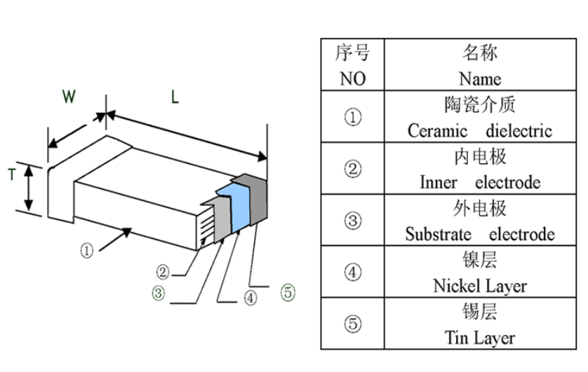
Electrode materials

The main component of a capacitor is the electrode, whose material is usually made of highly conductive metals, such as aluminum, tantalum, etc. These metals are treated with special chemicals to form extremely thin metal foils, thereby increasing the surface area of the electrode and improving the energy storage density of the capacitor.

Electrolytes

The electrolyte is another important component in a capacitor, and its role is to form a conductive path between the two electrodes. Depending on the type of electrolyte, capacitors can be divided into many types, such as electrolytic capacitors, ceramic capacitors, plastic film capacitors, etc. The electrolyte can be liquid, solid or gel, and its chemical composition determines the performance parameters of the capacitor, such as capacitance, operating voltage, temperature coefficient, etc.

Chip Capacitor Electronic Components Procurement - Chip Capacitor Manufacturers and Suppliers

Packaging materials

In order to protect the internal structure of the capacitor and facilitate its use, packaging materials are usually added to the outside. The packaging materials are mostly plastic or ceramic, which have good insulation and mechanical strength. The choice of packaging material also affects the performance and service life of the capacitor.

Analysis of the working principle of capacitors

Energy storage principle of capacitor

When a voltage is applied across the capacitor, the charges on the electrodes will move into the electrolyte under the action of the electric field force, forming a charge layer opposite to the applied voltage. This process allows the capacitor to store electrical energy. Capacitance is an important parameter that measures the ability of a capacitor to store electrical energy, and its unit is usually Farad (F). The size of the capacitance depends on factors such as the conductivity of the electrode material, the composition of the electrolyte, and the distance between the electrodes.

The charging and discharging process of capacitor

When the applied voltage changes, the capacitor will undergo a charge and discharge process. During the charging process, the applied voltage gradually increases, causing the charge on the electrode to continue to increase until an equilibrium state is reached. At this time, the voltage across the capacitor is equal to the applied voltage, and the energy stored in the capacitor reaches its maximum value. During the discharge process, the applied voltage gradually decreases or disappears, and the charge on the electrode is gradually released through the load in the circuit until the voltage across the capacitor drops to zero. This process realizes the conversion and transmission of electrical energy.

Frequency characteristics of capacitor

Due to the energy storage and discharge functions of capacitors in circuits, they have specific frequency characteristics. For high-frequency signals, the capacitor has a small impedance and can be used as a bypass component in the circuit; while for low-frequency signals, the capacitor has a large impedance and can be used as a DC-blocking component in the circuit. This frequency characteristic makes capacitors widely used in electronic circuits.

Conclusion and Outlook

This article provides an in-depth analysis of capacitors from two aspects: chemical element composition and working principle. By understanding the composition materials and energy storage principles of capacitors, we can better understand their role and application in electronic circuits. In the future, with the continuous advancement of science and technology and the emergence of new materials and new processes, the performance and types of capacitors will become more diverse. This will bring more choices and possibilities in the design and manufacturing of electronic circuits.

Is there any relationship between capacitor packaging material and temperature?

There is a certain relationship between capacitor packaging materials and temperature.

First, the choice of packaging material will affect the temperature resistance of the capacitor. Different packaging materials have different thermal expansion coefficients and thermal conductivity properties, which will affect the temperature range and service life of the capacitor. For example, some capacitors encapsulated in metal shells have good high temperature resistance, while some capacitors encapsulated in plastic shells may be affected by high temperatures and cause deformation or aging.

Secondly, the thermal conductivity of the packaging material will also affect the temperature stability of the capacitor. If the thermal conductivity of the packaging material is poor, the heat generated by the capacitor during operation may not be transferred out in time, causing the internal temperature of the capacitor to rise, thereby affecting its performance and service life.

Chip capacitor structure diagram - Chip capacitor appearance design structure diagram

In addition, the insulation properties of the packaging material will also affect the temperature resistance of the capacitor. If the insulation performance of the packaging material is poor, the capacitor may be affected by the external environment during operation and cause problems such as leakage or short circuit, thus affecting its temperature resistance and service life.

To sum up, there is a certain relationship between capacitor packaging materials and temperature. Choosing the appropriate packaging material can ensure the temperature resistance and service life of the capacitor. At the same time, when using capacitors, you also need to pay attention to factors such as its working environment temperature and service life to avoid affecting its performance and service life due to too high or too low temperature.

What are the effects of capacitor packaging materials and packaging processes?

The packaging material and packaging process of the capacitor have an important impact on its performance and service life.

First, the choice of packaging materials affects the electrical properties, mechanical properties and environmental adaptability of the capacitor. For example, metal packaging materials have good thermal and electrical conductivity, which can effectively protect the internal structure of the capacitor and improve its electrical and mechanical properties. Plastic packaging materials have the advantages of low cost, light weight, and corrosion resistance, but their mechanical strength and electrical properties are relatively poor.

Secondly, the packaging process will also affect the performance and service life of the capacitor. Different packaging processes will lead to differences in the size, weight, electrical performance and mechanical properties of capacitors. For example, the leaded packaging process has higher production efficiency and lower cost, but the capacitor is larger and may have larger parasitic inductance problems in high-frequency circuits. The chip packaging process can make the capacitor smaller, lighter, and have smaller parasitic inductance, making it more suitable for use in high-frequency circuits.

In addition, the packaging process also affects the reliability of the capacitor. For example, during the welding process, if the welding is poor or the welding time is too long, it may cause damage to the internal structure of the capacitor or reduce its performance. At the same time, during the assembly process, if the assembly is improper or inappropriate fasteners are used, the capacitor may also become loose or damaged.

To sum up, the packaging materials and packaging processes of capacitors have an important impact on their performance and service life. When selecting packaging materials and packaging processes, comprehensive considerations need to be made based on specific application scenarios and needs to ensure the optimal performance and service life of the capacitor.

Is there any relationship between capacitor packaging material and frequency?

There is a certain relationship between capacitor packaging materials and frequency.

First, different packaging materials have different electrical performance parameters such as dielectric constant and loss tangent value. These parameters will affect the equivalent series resistance (ESR) and equivalent series inductance (ESL) of the capacitor, thereby affecting the frequency response characteristics of the capacitor.

Secondly, the packaging process will also affect the frequency response characteristics of the capacitor. For example, the parasitic inductance of the lead-type packaging process is larger, while the parasitic inductance of the patch-type packaging process is smaller. These parasitic inductances will affect the frequency response characteristics of the capacitor, causing its performance to degrade in high-frequency circuits.

In addition, packaging materials and processes can also affect the stability of the capacitor. For example, some metal-cased capacitors may be affected by oxidation or corrosion in high-temperature environments, resulting in a decrease in their electrical performance. Some capacitors encapsulated in plastic shells may be affected by temperature changes and cause problems such as aging or deformation.

To sum up, there is a certain relationship between capacitor packaging materials and frequency. When selecting a capacitor, comprehensive considerations need to be made based on specific application scenarios and needs to ensure that the frequency response characteristics and stability of the capacitor are optimal.

Top 10 capacitor manufacturers and suppliers in China

Fujian Torch Electronic Technology Co., Ltd.

Torch Electronics is an enterprise focusing on the R&D, manufacturing, sales and service of capacitors. The company was established on December 20, 2007 and is headquartered in Fuzhou City, Fujian Province.

Torch Electronics’ capacitor products are widely used in aviation, aerospace, shipbuilding, communications, electric power, rail transportation, new energy and other fields. In addition, the company also has 7 wholly-owned subsidiaries and 2 holding subsidiaries, mainly engaged in capacitor R&D, manufacturing, sales and service.

Fujian Torch Electronic Technology Co., Ltd. - Chip Capacitor Manufacturers and Suppliers in China

In terms of technology, Torch Electronics has advanced technology and R&D capabilities, and its products are popular for their leading technology and reliable quality. In addition, the company also focuses on marketing concepts and service follow-up, and is committed to pursuing multi-win situations to meet customer needs.

Nantong Jianghai Capacitor Co., Ltd.

Nantong Jianghai Capacitor Co., Ltd. is an enterprise mainly engaged in the production, sales and service of capacitors, their materials and accessories. The company was founded in 1958 and began specializing in the production of aluminum electrolytic capacitors in 1970. The company currently occupies an area of 120,000M2, with a building area of 60,000M2, more than 1,200 employees, and five joint venture affiliated companies. It is a national high-tech enterprise and a key enterprise of the National Torch Plan-Tongzhou Electronic Components and Materials Industry Base.
In terms of products, the aluminum electrolytic capacitors of Nantong Jianghai Capacitor Co., Ltd. have excellent self-healing characteristics, high reliability, and high cost performance. They are widely used in industrial controllers, various power supplies, new energy, white goods, military industry and other fields. . In addition, the company’s metallized film capacitors have the characteristics of small equivalent series resistance, large ripple current tolerance, self-healing, good safety features, and long service life. They are widely used in power electronics, new energy, and military industries. and other fields.
In terms of honors, Nantong Jianghai Capacitor Co., Ltd. has been selected as one of the top 100 enterprises in China’s electronic components industry selected by the China Electronic Components Industry Association for many consecutive years. In addition, the company has ranked first in the domestic aluminum electrolytic capacitor industry in terms of sales revenue since 1993. In September 2010, it was listed on the SME Board of the Shenzhen Stock Exchange.
Nantong Jianghai Capacitor Co., Ltd. has rich experience and good performance in the field of capacitors, and is a capacitor supplier worth considering.

Aihua

Aihua Capacitor Co., Ltd. is a company specializing in the production and sales of aluminum electrolytic capacitors. It has a complete industrial chain from corrosion foil, chemical foil to aluminum electrolytic capacitors, and independently develops a capacitor quality management software system. The company is committed to providing high-quality aluminum electrolytic capacitors to the world. After years of development, the company continues to improve and develop new products, and its independent innovation capabilities continue to increase.

Fara Electronics

Xiamen Fara Electronics Co., Ltd. is a listed company specializing in the development and production of film capacitors and metallized films for film capacitors. The company has a strong R&D center and an experienced technical service team, with an annual output of 4.5 billion film capacitors and 2,500 tons of metallized films. The company’s products are widely used in communications, home appliances, lighting, automobiles, industrial control and other fields, and have passed ISO9001 quality system certification, ISO14001 environmental management system certification, and OHSAS18001 occupational health and safety management system certification.

Shenzhen Jinpenghui Technology Co., Ltd.

Shenzhen Jinpenghui Technology Co., Ltd. is a high-tech company integrating R&D and sales, located in Shenzhen, Guangdong Province. The company mainly sells Zhaoqing emerald electrolytic capacitors, emerald capacitors, BERYL electrolytic capacitors, KFSON capacitors, Kangfusong electrolytic capacitors, solid electrolytic capacitors, solid capacitors and other products. These products are widely used in LED light driving power supplies, electronic energy-saving lamps and ballasts, stage amplifiers, vehicle electronic equipment, computer motherboards, security products, inverters, network communications, medical equipment power supplies, UPS and other fields.

Fenghua Hi-Tech

Guangdong Fenghua High-tech Co., Ltd. is a company specializing in the development, design, manufacturing and sales of electronic components and materials, and integrated circuits. Its products are widely used in communications, consumer electronics, computers, automotive electronics, new energy and other fields.
One of the largest manufacturers of passive electronic components in China, its main products include capacitors, resistors, inductors, etc.

Beijing Yuanliu Hongyuan Electronic Technology Co., Ltd.

Beijing Yuanliu Hongyuan Electronic Technology Co., Ltd. is a high-tech enterprise of electronic components mainly engaged in the development, production and operation of multi-layer (chip) ceramic capacitors. The company is headquartered in Fengtai Science and Technology Park, Zhongguancun, Beijing, and its production base is built in Jinnan Shuanggang Economic Development Zone, Tianjin.
For many years, the company has been committed to the R&D and production of multilayer ceramic capacitors. It has a complete multilayer ceramic capacitor production line and has routine experiments, destructive physical analysis (DPA) and material (chip) electrical and process performance certification. Three key laboratories and a number of domestic and foreign advanced equipment and facilities provide a strong guarantee for ensuring product quality.

Tongfeng Electronics

Anhui Tongfeng Electronics Co., Ltd. (hereinafter referred to as: Tongfeng Electronics) is a company engaged in the research, development, production and sales of film capacitors and film materials. It has advantages in technology and research and development, integrated industrial chain, and brand.

Three-Circle (Group)

Chaozhou Three-Circle (Group) Co., Ltd. was established in 1970 and listed on the Shenzhen Stock Exchange in 2014 (stock code: 300408). It is a company dedicated to the research and development, production and sales of electronic basic materials, electronic components, communication devices and other products. comprehensive enterprise. The company’s products cover many application fields such as optical communications, electronics, electrical engineering, machinery, energy conservation and environmental protection, new energy and fashion. Among them, the production and sales of optical fiber connector ceramic ferrules, alumina ceramic substrates, and ceramic substrates for resistors rank among the top in the world. The company has been rated as a national technology enterprise and a single champion demonstration enterprise in China’s manufacturing industry. It has been ranked among the top ten of China’s top 100 electronic components for many consecutive years.

Yageo

Yageo Co., Ltd. is the world’s leading brand of passive components. Founded in 1977, it is Taiwan’s first listed electronic components company. Yageo Electronics (Suzhou) Co., Ltd. is a wholly-owned subsidiary of Yageo Co., Ltd. in China. It was registered and established in March 2001. The company’s business scope includes the production of electronic components, new electronic components, new instrument circuit boards, etc.

In addition, Yageo Co., Ltd. has also launched products such as tantalum nitride films and high-precision resistors with anti-humidity and anti-sulfur properties.

Yageo Co., Ltd. was founded in 1977. It is the largest supplier of passive components in Taiwan and the largest professional capacitor manufacturer in the world. It is Taiwan’s first listed passive component and is an international enterprise with global production and sales bases.

How to choose high-quality, highly integrated chips?

XPD938 chip - How to choose high-quality, highly integrated chips?

When purchasing high-quality, highly integrated chips, you need to consider many aspects, including brand reputation, specifications, performance testing, quality assurance and after-sales service.

Choosing a well-known brand or certified chip supplier can ensure you get high-quality chips. At the same time, carefully check the specifications of the chip to ensure that it meets the application requirements. Conducting performance tests can help you understand the performance of the chip and select a chip with high performance.

How to choose high-quality, highly integrated chips?

In addition, confirm whether the chip has passed quality certification and choose a supplier that provides good after-sales service so that any problems encountered during use can be solved in a timely manner. To sum up, when purchasing high-quality, highly integrated chips, multiple factors need to be considered to ensure a high-quality product.
Next, let’s take a look at the concept of highly integrated chips, how to purchase highly integrated chips, and the comparison between highly integrated and low-integrated chips.

What is a highly integrated chip

Highly integrated chips refer to the integration of more functional modules or circuits on one chip, thereby enabling more complex functions. Integration refers to how many functional modules or circuits are integrated into a chip, which can also be understood as the number of components on the chip. High integration means that more functional modules or circuits are integrated on one chip, allowing more complex functions to be implemented.

How to choose high-quality, highly integrated chips?

To purchase high-quality, highly integrated chips, you can consider the following aspects:

  1. Brand reputation: Choosing a well-known brand or a certified chip supplier can ensure you get high-quality chips.
  2. Specifications: Carefully check the specifications of the chip, including operating voltage, current, frequency, storage capacity, etc., to ensure that it meets your application needs.
  3. Performance test: Conduct a performance test before purchasing to understand the performance of the chip, such as computing speed, power consumption, etc., to ensure that it meets your expectations.
  4. Quality assurance: Confirm whether the chip has passed quality certification, such as ISO9001, etc., to ensure its reliable quality.
  5. After-sales service: Choose a supplier that provides good after-sales service so that problems encountered during use can be solved in a timely manner.

To sum up, when purchasing high-quality, highly integrated chips, you need to comprehensively consider many aspects such as brand reputation, specifications, performance testing, quality assurance and after-sales service.

High-quality, highly integrated chip - HX78L05 replaces Changdian CJ78L05. Negotiable price with 30V withstand voltage in large quantities

Highly integrated chips refer to chips that integrate multiple functional modules on the same chip. They have the advantages of small size, low power consumption, and low cost. When purchasing highly integrated chips, you need to consider the following factors:

Whether the functions of the chip meet the needs: Highly integrated chips can provide a variety of functions, and users need to choose the appropriate chip according to their actual needs. For example, if you need to design a smart speaker, you need to choose a chip that integrates audio processing, speech recognition, speech synthesis and other functions.

Whether the performance of the chip meets the requirements: The performance indicators of highly integrated chips include operating frequency, power consumption, computing power, etc. Users need to choose a chip with performance that meets their requirements based on their own application scenarios. For example, if you need to design a high-definition video player, you need to choose a chip with high operating frequency and strong computing power.

Chip stability and reliability: Highly integrated chips have a high degree of integration, and there are certain risks in the design and manufacturing process. Users need to choose chips with good stability and reliability to ensure the normal operation of the product. For example, you can choose chips with longer market validation.

Cost of chips: The cost of highly integrated chips is usually higher. Users need to choose a cost-effective chip based on their own budget.

Specifically, you can follow the following steps to purchase:

  1. Clarify your needs: First of all, you must clarify your own needs and what functions you need a highly integrated chip to achieve.
  2. Collect information: Collect information about related chips, including chip functions, performance, stability, reliability, cost, etc.
  3. Comparative analysis: Comparatively analyze the performance, price, etc. of different chips, and choose the chip that best meets your needs.

The following are some considerations when purchasing highly integrated chips:

Choose chips from well-known manufacturers: Chips from well-known manufacturers usually have better performance, stability and reliability.

Pay attention to the technological progress of chips: The technology of highly integrated chips continues to develop. Users need to pay attention to the latest technological trends and choose the most advanced chips.

Analysis of reasons for purchasing highly integrated chips

Pay attention to the compatibility of the chip: Highly integrated chips usually need to be paired with other hardware to work. Users need to pay attention to the compatibility of the chip.

Analysis of reasons for purchasing highly integrated chips

The main reasons for purchasing highly integrated chips are as follows:

  1. Performance improvement: Highly integrated chips can integrate more functional modules or circuits, thereby enabling more complex functions and improving chip performance.
  2. Reduce costs: Highly integrated chips can reduce the number and types of external components, thereby reducing the cost of the entire system.
  3. Reduce the size: Highly integrated chips can reduce the size of the entire system, making it easier to carry and use.
  4. Improve reliability: Highly integrated chips use advanced materials and technologies and have high reliability and stability, which can improve the reliability of the entire system.

To sum up, purchasing highly integrated chips can improve performance, reduce costs, reduce size and improve reliability, which is an important trend in the development of modern electronic equipment.

What is the difference between a highly integrated chip and a low-integrated chip?

The main differences between highly integrated chips and low-integrated chips are as follows:

  1. Size and weight: Highly integrated chips usually have smaller size and lighter weight because they integrate more functional modules or circuits and can achieve higher performance in a smaller space. Chips with low integration are usually larger in size and heavier in weight.
  2. Performance and power consumption: Highly integrated chips can provide higher performance and lower power consumption because they integrate more functional modules or circuits. They typically have higher clock frequencies and lower latency, allowing them to process data and instructions faster. Chips with low integration have relatively low performance and relatively high power consumption.
  3. Reliability and stability: Highly integrated chips use advanced materials and technologies and have high reliability and stability. They undergo strict testing and quality control to ensure normal operation in harsh working environments. Chips with low integration may have some potential problems, such as thermal stability, electrical performance, etc., and require more maintenance and debugging during use.
  4. Cost and selling price: Due to the use of advanced materials and technologies, highly integrated chips have relatively high manufacturing costs, so the selling price is also relatively high. Chips with low integration have relatively low manufacturing costs and relatively low selling prices.

To sum up, there are certain differences in size, performance, reliability, cost, etc. between highly integrated chips and low-integrated chips. When selecting a chip, you need to comprehensively consider the specific application scenarios and needs to select the most suitable chip type and supplier.

Voltage regulator module for in-vehicle computers

Voltage regulator module for in-vehicle computers

The voltage regulator module is an indispensable component in the on-board computer. Its main function is to stabilize the power supply voltage and ensure that the on-board computer can work normally in various environments.

Industrial grade DC step-down module 5V/12V/24V/6A 8A voltage regulator module design circuit diagram

In vehicle-mounted computers, fluctuations and instability in the power supply voltage may affect the operation of the computer or even cause the computer to malfunction.

Therefore, the role of the voltage regulator module is crucial. It can stabilize the power supply voltage within a certain range, ensure the normal operation of the on-board computer, and improve its stability and reliability.

Industrial grade DC step-down module 5V/12V/24V/6A 8A

At the same time, the voltage regulator module also has functions such as over-current protection and over-voltage protection, which can cut off the power supply in time when the power supply is abnormal and protect the on-board computer from damage. Therefore, the voltage regulator module is an indispensable and important component in the on-board computer.

Voltage Regulator Module Manufacturer in China

Which voltage regulator module packaging method is more suitable for vehicle-mounted computers?

In on-board computers, surface mount package (SMT) voltage regulator modules are more suitable. The following is a detailed analysis and explanation:

Environmental requirements for on-board computers

Vehicle-mounted computers usually need to work in harsh environments, such as high temperature, low temperature, vibration, etc. Therefore, there are high requirements for the packaging method of electronic components.

Comparison of through-hole and surface mount packages

Direct plug-in package

Advantages: The initial cost of plug-in packaging is relatively low due to its simple design and installation method.

Comparison of through-hole and surface mount packages

Disadvantages: Due to its large size, it may not be suitable in compact vehicle environments. In addition, because it is directly exposed to the external environment, it is easily affected by vibration, dust, etc., resulting in unstable performance.

Voltage Stabilizer Chip Module Supplier - Stabilized DC-DC High Power Voltage Buck PCB Board - Voltage Stabilizer Module Manufacturer in China

Surface mount package

Advantages: Surface mount packages are small and lightweight, saving valuable circuit board space. In addition, due to its tight packaging, it can effectively resist the influence of external environment, such as vibration, dust, etc.

Disadvantages: Surface mount packages are more expensive to manufacture than through-hole packages.

Advantages of surface mount packaging in automotive computers

  1. Save space: In on-board computers, space is usually very limited. The use of surface mount packaged voltage regulator modules can effectively save circuit board space, leaving more space for layout of other electronic components.
  2. Improve reliability: Since the surface mount package can effectively resist the influence of the external environment, the reliability of the voltage regulator module can be significantly improved. This is critical for in-vehicle computers operating in harsh environments.
  3. Easy to integrate and repair: Surface mount packaging allows multiple voltage regulator modules and other electronic components to be easily integrated into one module, thus simplifying the circuit board layout and repair process.

Which brand of voltage regulator module is better to choose for on-board computers?

When choosing a voltage regulator module for an on-board computer, you need to consider multiple factors, including brand, performance, reliability, stability, etc. The following are some well-known voltage regulator module brands in the market for your reference:

Delixi Electric

Delixi Electric is a Sino-French joint venture that focuses on providing comprehensive solutions in the fields of low-voltage power distribution and industrial automation. Its voltage regulator module has been widely used in on-board computers with stable performance and high reliability.

Chint

Chint is a platform enterprise with new energy, energy distribution, big data, and energy value-added services as its core businesses. Its voltage regulator module also has high cost performance and stability in on-board computers.

UNO R3 development board project - component procurement and assembly

Hongbao

Hongbao is a large-scale enterprise specializing in R&D, manufacturing, sales and service in the power supply field. Its voltage regulator module has high power density and stability in on-board computers.

Tianzheng

Tianzheng is a well-known low-voltage electrical appliance brand under Tianzheng Group, specializing in the R&D, production and sales of medium and low-voltage smart appliances/intelligent meters/inverters and other electrical products. Its voltage regulator module also has high performance and reliability in on-board computers.
The above brands all provide high-quality voltage regulator module products, but you need to consider comprehensively based on your specific needs and budget when choosing. It is recommended that you carefully compare different product performance, price, after-sales service and other factors before purchasing to ensure that you choose the most suitable voltage regulator module for your application.

What are the car voltage regulator chip models?

There are many models of automotive voltage regulator chips. The following are some common models:

TPS74525PQWDRVRQ1

Linear regulator IC, 2.5V, 500MA, 6W, SON package.

TPS745-Q1

Adjustable 500mALDO regulator with extremely low quiescent current, fast line and load transient performance, ultra-low dropout voltage of 130mV (500mA current), helping to improve system power efficiency, small 6-pin, 2mm × 2mm WSON package.

UNO R3 Development Board Improved Version Enhanced Version ATmega328PB Microcontroller Blue Board - Electronic Component Module

TPS62992-Q1

Automotive buck converter, easy-to-use small package size, high efficiency and flexibility, output voltage 400mV ~ 5.5V, output current 2A, number of output terminals 1, input voltage 3V ~ 10V, switching frequency 1MHz or 2.5MHz, VQFN -9 packages.

TPS7A66-Q1 and TPS7A69-Q1

Low dropout linear regulator designed for operating circuits with input voltages up to 40V, with a quiescent current of only 12μA at no load, making it ideal for standby microprocessor control unit systems, especially in automotive applications where low power consumption is a key issue .

in conclusion

All things considered, surface mount packaged voltage regulator modules are more suitable for use in automotive computers. Its small size, light weight, and high reliability give it advantages in compact and harsh vehicle environments.

Voltage regulator module for in-vehicle computers

However, when selecting a packaging method, other factors need to be considered, such as cost, production capacity, etc., to ensure that the final packaging method selected is best suited for specific application requirements.

How to manufacture voltage regulator chip and analysis of its principles

Voltage regulator chip circuit design layout structure diagram

A voltage regulator chip is an electronic device used to stabilize voltage and is widely used in various electronic devices. Its manufacturing process involves multiple complex technical links, including material preparation, chip design, manufacturing process, testing, etc.

The manufacturing process and principles of the voltage regulator chip will be introduced in detail below.

Explain how the voltage regulator chip is manufactured and its principle analysis

The manufacturing method of voltage stabilizing chips includes chip design, manufacturing process and packaging testing. Chip design is a key step, and the circuit diagram and layout are designed according to application requirements.

The manufacturing process includes complex steps such as photolithography, etching, and ion implantation to transfer the designed layout to the silicon wafer to create circuit structures and components. Package testing involves packaging the chip in an appropriate package and testing it to ensure performance and stability.

The principle of the voltage stabilizing chip is to maintain a stable output voltage through internal circuit regulation.

The error amplifier detects the difference between the input voltage and the output voltage, and the adjustment tube adjusts the on-resistance according to the error signal to stabilize the output voltage.

Next, we will introduce in detail the manufacturing method and principle analysis of the voltage stabilizing chip.

Voltage regulator chip manufacturing material preparation

The main materials of voltage regulator chips include semiconductor materials, metal materials and ceramic materials. Among them, semiconductor materials are the core part of the chip. Commonly used semiconductor materials include silicon, germanium, etc. Metal materials are used to manufacture chip pins and heat sinks, while ceramic materials are used to manufacture chip packaging casings.

Voltage regulator chip design

The design of the voltage regulator chip mainly includes circuit design and layout design. Circuit design is to design the corresponding circuit diagram based on the functional requirements of the voltage regulator and determine the parameters and connection methods of each component.

Voltage regulator chip circuit design layout structure diagram

Voltage regulator chip circuit design layout structure diagram – Instructions for use of the 5V voltage regulator chip L5300AH with built-in thermal protection function

Layout design is to transform the circuit design into a specific physical structure, including the layout and wiring of components.

Voltage regulator chip manufacturing process

The manufacturing process of voltage regulator chips mainly includes thin film manufacturing, photolithography, etching, doping, etc.

  1. Thin film manufacturing: Through methods such as chemical vapor deposition or physical vapor deposition, a thin film of a certain thickness is formed on the surface of the chip. These thin films can be semiconductor materials, metal materials or insulating materials, etc.
  2. Photolithography: The designed circuit diagram is transferred to the chip surface through photolithography technology to form a mask for the circuit pattern.
  3. Etching: Using chemical or physical methods to remove unnecessary materials to form circuit patterns.
  4. Doping: By adding impurity elements to semiconductor materials, their conductive properties are changed to achieve circuit functions.

Voltage regulator chip testing and quality inspection

After manufacturing is completed, the voltage regulator chip needs to be tested to ensure that its performance and quality meet requirements. Testing includes electrical performance testing, reliability testing, environmental adaptability testing, etc.

Voltage regulator chip packaging and aging analysis

The voltage regulator chip that has passed the test needs to be packaged and aged. Packaging is to fix the chip in a package shell to protect the chip from the external environment. Aging is to run the chip under certain temperature and humidity conditions for a long time to test its stability and reliability.

What are the packaging methods of voltage regulator modules?

The packaging methods of voltage regulator modules mainly include the following:

Direct plug-in package

This packaging method inserts the voltage regulator chip directly into the socket on the circuit board and connects to the circuit board through pins. In-line packaging has the advantages of simple installation and low cost, but it takes up a lot of circuit board space.

surface mount package

Surface mount packaging is a packaging method in which the voltage regulator chip is directly soldered to the surface of the circuit board. This packaging method has the advantages of small size, light weight, and high reliability, so it has been widely used in electronic equipment.

Module packaging

Module packaging is to assemble multiple voltage regulator chips and other electronic components into a module, and then connect them to the circuit board through pins. Module packaging has the advantages of high integration and easy maintenance, so it has been widely used in some complex circuits.

Different packaging methods are suitable for different applications and different electronic devices. When selecting the packaging method of the voltage regulator module, comprehensive considerations need to be made based on factors such as specific application requirements and circuit board space.

Voltage regulator chip packaging process

The packaging process of the voltage regulator chip mainly includes pin welding, shell packaging, marking and other links.

  1. Pin welding: Weld the pins of the chip to the pins of the package shell to connect the chip to the external circuit. Pin welding can be done manually or automatically.
  2. Shell packaging: The chip is placed in the packaging shell, and the pins of the shell are connected to the pins of the chip. At the same time, the protection of the shell prevents the chip from being affected by the external environment. The shell package can be made of metal, ceramics and other materials.
  3. Marking: After the packaging is completed, the chip surface needs to be marked, including chip model, production date and other information, for subsequent identification and use.

Principle Analysis of Voltage Regulator Chip

The principle of voltage regulator chips is mainly based on voltage regulation and current limiting. Through the regulation of the internal circuit, the output voltage is maintained within a stable range while limiting the output current to not exceed a safe range. Specifically, voltage regulator chips typically use linear or switching power supply technology to achieve voltage regulation and current limiting. Linear voltage regulators use linear adjustment tubes to adjust the output voltage, which have the advantages of low power consumption and low noise; switching power supply voltage regulators use switching tubes to adjust the output voltage, which have the advantages of high efficiency and small size.

In the voltage regulator chip, the realization of voltage regulation and current limitation also involves some key technical links, such as error amplifier, comparator, power tube, etc. The error amplifier is used to detect the error between the output voltage and the reference voltage, and amplify the error signal and pass it to the comparator; the comparator compares the error signal with the internal reference voltage, and controls the on and off of the power tube based on the comparison result; The power tube adjusts the output voltage and current according to the control signal of the comparator.

In short, the manufacturing process of voltage regulator chips involves many complex technical links, including material preparation, chip design, manufacturing process, testing, etc. Its principle is mainly based on the realization of voltage regulation and current limitation. Through the regulation of the internal circuit, the output voltage is maintained within a stable range and the output current is limited to not exceed a safe range.

Precautions for voltage regulator chip packaging process

When performing the packaging process of the voltage regulator chip, you need to pay attention to the following points:

  1. When welding pins, ensure the welding quality and avoid virtual welding, cold welding and other phenomena.
  2. When encapsulating the shell, ensure sealing to prevent moisture, dust, etc. from entering the inside of the chip.
  3. Marking should be clear and accurate to facilitate subsequent identification and use.

Development Trend of Voltage Regulator Chip Packaging Process

With the continuous development of technology, the packaging process of voltage regulator chips is also constantly improving. In the future, as chip sizes continue to shrink and integration levels continue to increase, the requirements for packaging processes will become more stringent. Therefore, it is necessary to continuously improve and optimize the packaging process to improve production efficiency and product quality. At the same time, with the continuous improvement of environmental awareness, green and environmentally friendly packaging materials and processes will also become a future development trend.

Study the manufacturing processes of electronic component manufacturers

Study the manufacturing processes of electronic component manufacturers

The manufacturing process of electronic component manufacturers is the key to the quality of electronic products. The process involves multiple links from raw material preparation to finished product assembly, including cutting, forming, processing, welding, etc.

High-quality materials and advanced equipment are the basis of manufacturing, while technology is the core. In the future, intelligent manufacturing, green manufacturing and personalized customization will become trends.

3*8 32.768KHZ crystal cylindrical quartz 32768 crystal

Summary

This article studies the manufacturing process of electronic component manufacturers, including manufacturing processes, equipment, materials, technology, etc. By comparing and analyzing the manufacturing processes of different manufacturers, this article summarizes the characteristics and trends of electronic component manufacturing processes, and puts forward corresponding suggestions and improvement measures.

Keywords: electronic components, manufacturing technology, manufacturing process, equipment, materials, technology

introduction

Electronic components are the core components of electronic products, and their manufacturing process is crucial to the performance and quality of the product. With the continuous development of science and technology, the manufacturing process of electronic components is also constantly improving and improving. This article aims to study the manufacturing processes of electronic component manufacturers and provide reference and reference for related companies and researchers.

Overview of electronic component manufacturing process

The manufacturing process of electronic components mainly includes manufacturing processes, equipment, materials and technologies. The manufacturing process refers to the entire process from raw materials to finished products, including raw material preparation, processing, assembly, testing and other links. Equipment is an important tool in the manufacturing process, including various machine tools, molds, fixtures, etc.

Electronic component design and schematic design

Materials are the basis of the manufacturing process, including conductive materials, insulating materials, magnetic materials, etc. Technology is the core of the manufacturing process, including manufacturing technology, detection technology, control technology, etc.

Comparison and analysis of electronic component manufacturing processes

Manufacturing process of electronic components

Different manufacturers have differences in their manufacturing processes, but generally they follow the process from raw material preparation to finished product assembly. Among them, the raw material preparation link includes procurement, inspection, storage, etc.; the processing link includes cutting, forming, processing, etc.; the assembly link includes welding, assembly, testing, etc.; the testing link includes functional testing, performance testing, etc.

Equipment required for electronic components

Different manufacturers also have differences in equipment, but generally they use advanced equipment and technology. Among them, cutting equipment includes laser cutting machines, mechanical cutting machines, etc.; molding equipment includes stamping machines, injection molding machines, etc.; processing equipment includes milling machines, lathes, etc.; welding equipment includes automatic welding machines, manual welding stations, etc.

Materials required for manufacturing electronic components

There are also differences in materials between different manufacturers, but generally they all use high-quality materials. Among them, the conductor materials use metal materials such as copper and aluminum; the insulating materials use polymer materials such as polyimide (PI) and polytetrafluoroethylene (PTFE); the magnetic materials use ferrite, neodymium iron boron, etc.

Electronic component manufacturing technology

There are also differences in technology between different manufacturers, but generally they all use advanced manufacturing technology. Among them, manufacturing technology includes precision processing technology, surface treatment technology, etc.; detection technology includes X-ray detection technology, ultrasonic detection technology, etc.; control technology includes computer-aided design (CAD), computer-aided manufacturing (CAM), computer-aided process planning (CAPP) )wait.

Electronic component manufacturing process characteristics and trends

Characteristics of electronic component manufacturing

(1) High precision: With the improvement of the performance of electronic products, the precision of electronic components is getting higher and higher, which requires the use of high-precision manufacturing equipment and processes.

(2) High efficiency: In order to meet market demand and improve competitiveness, the manufacturing of electronic components needs to achieve high-efficiency production.

(3) Environmental protection: With the improvement of environmental awareness, the manufacturing of electronic components needs to use environmentally friendly materials and processes to reduce the impact on the environment.

Trends in electronic component manufacturing

(1) Intelligent manufacturing: With the development of artificial intelligence technology, the manufacturing of electronic components will realize intelligent production, improving production efficiency and product quality.

(2) Green manufacturing: With the improvement of environmental awareness, the manufacturing of electronic components will use more environmentally friendly materials and processes to achieve green production.

(3) Personalized customization: With the diversification of consumer needs, the manufacturing of electronic components will realize personalized customized production to meet the needs of different customers.

Suggestions and improvement measures

Strengthen technological innovation

Enterprises should strengthen technological innovation and research and development, improve the technical level of manufacturing processes, reduce production costs and improve product quality.

Optimize manufacturing processes

Enterprises should optimize and improve manufacturing processes to improve production efficiency and quality levels. For example, advanced management methods and technical means such as concurrent engineering and lean production can be adopted.

Use advanced equipment

Enterprises should adopt advanced equipment and process technology to improve production efficiency and product quality levels. For example, advanced production equipment and technical means such as automated production lines and robots can be used.

Strengthen quality management

Enterprises should strengthen quality management and establish complete quality management systems and testing methods to ensure that product quality meets standards and customer requirements. For example, advanced management methods and technical means such as total quality management (TQM) and Six Sigma management can be adopted.

Difficulties and challenges in studying electronic component manufacturing processes

The difficulties and challenges in studying electronic component manufacturing processes mainly include the following aspects:

  1. Rapid technological updates: With the rapid development of science and technology, the manufacturing process of electronic components is also constantly updated. This means that researchers need to constantly learn and master new technologies to adapt to changing market needs.
  2. High equipment investment costs: The update of manufacturing processes often requires advanced equipment support. The procurement and maintenance costs of these equipment are usually high, which puts certain economic pressure on enterprises.
  3. Unstable supply of raw materials: The manufacturing of electronic components requires high-quality raw materials, and the supply of these raw materials is often affected by a variety of factors, such as market supply and demand, international trade policies, etc., resulting in unstable supply of raw materials.
  4. Increased environmental protection requirements: With the improvement of environmental awareness, the manufacturing process of electronic components needs to pay more attention to environmental protection and sustainable development. This requires companies to take more environmental protection measures during the production process to meet increasingly stringent environmental regulations.
  5. Diversified market demand: Different customers have different demands for electronic components, requiring companies to provide diversified products and services. This brings certain challenges to the company’s R&D and production, and the manufacturing process needs to be continuously adjusted and optimized to meet market demand.
Study the manufacturing processes of electronic component manufacturers

In order to deal with these difficulties and challenges, companies can take the following measures:

  1. Strengthen technological R&D and innovation: By increasing investment in technological R&D and innovation, we will improve the technological level and core competitiveness of enterprises to adapt to changing market demands.
  2. Optimize equipment configuration and update: According to the actual situation of the enterprise and market trends, rationally configure and update equipment to improve equipment usage efficiency and economic benefits.
  3. Strengthen supply chain management: establish stable cooperative relationships with suppliers to ensure stable supply and quality assurance of raw materials.
  4. Promote environmental protection concepts: Actively promote environmental protection concepts during the production process, adopt environmental protection measures, and reduce environmental pollution during the production process.
  5. Improve customized service capabilities: Strengthen communication and cooperation with customers, improve customized service capabilities, and meet the diverse needs of customers.

The best solution for researching electronic components

The best solution for researching electronic components

Electronic components are the basis of electronic equipment and have an important impact on the performance, stability, and reliability of electronic equipment.

With the continuous development of science and technology, the types and performance of electronic components are also constantly updated and improved. Therefore, the research on electronic components is particularly important. This article will explore the best options for researching electronic components.

Electronic Component Module Manufacturer - Component Supplier in China

Research purposes

The purpose of studying electronic components is to understand information about their performance, characteristics, application fields, etc., so as to better select and use electronic components and improve the performance and reliability of electronic equipment. At the same time, through the research on electronic components, new application fields and market demands can also be discovered, providing new ideas and directions for the development of electronic components.

Research methods

  1. Literature review

Through a review of relevant literature, we can understand the development history, technical characteristics, application fields and other information of electronic components, which will provide a basis for subsequent research.

  1. Experimental research

Through experimental research, the performance of electronic components is tested and analyzed to understand their performance and performance characteristics in practical applications. At the same time, potential problems and improvement directions for electronic components can also be discovered through experimental research.

  1. Simulation research

Use simulation software to simulate and analyze the working principles and performance of electronic components to understand their performance and performance characteristics in practical applications. At the same time, new application areas and market needs can also be discovered through simulation research.

  1. Market research

Through market research and analysis, we can understand the market demand, competitive situation, development trends and other information of electronic components to provide reference for subsequent research.

TD210N18KOF Infineon thyristor - new original electronic component power module

Research content

  1. Types and performance characteristics of electronic components

Through research and comparison of different types of electronic components, we can understand their performance characteristics and application fields. At the same time, different types of electronic components are classified and summarized for better selection and use.

  1. Application fields and development trends of electronic components

Through research and analysis on the application fields and development trends of electronic components, we can understand their future development direction and application prospects. At the same time, we forecast and analyze new application areas and markets to provide reference for subsequent research.

  1. Manufacturing process and technical characteristics of electronic components

Through research and analysis of the manufacturing processes and technical characteristics of electronic components, we can understand the key technologies and difficulties in their manufacturing process. At the same time, different manufacturing processes and technologies are compared and evaluated for better selection and use.

  1. Quality control and reliability assessment of electronic components

Through the research and analysis of quality control and reliability evaluation of electronic components, understand their performance and performance characteristics in practical applications. At the same time, different quality control and reliability assessment methods are compared and evaluated for better selection and use.

Conclusion and Outlook

Through research and analysis of electronic components, we can draw the following conclusions:

  1. The types and performance characteristics of electronic components are diverse, and they need to be selected and used according to actual needs.
  2. The application fields and development trends of electronic components are constantly changing, and it is necessary to pay attention to market dynamics and technological development.
  3. The manufacturing processes and technical characteristics of electronic components are diverse and need to be selected and used according to actual needs.
  4. Quality control and reliability evaluation of electronic components are key links to ensure their performance and stability.

Looking to the future, with the continuous development of science and technology, the performance and application fields of electronic components will become broader and deeper. At the same time, research on electronic components will also focus more on innovation and practicality. Therefore, we need to continuously strengthen research and innovation on electronic components to provide strong support for the development of future electronic equipment.

How to manually assemble electronic components onto a PCB board

PCB board - Preparation for manual assembly of electronic components

Manual assembly of electronic components onto PCB boards is an important electronic process technology.

By using suitable tools and materials, electronic components are placed on the PCB board one by one and soldering techniques are used to fix them in the correct position.

During the welding process, attention needs to be paid to the welding time and temperature to ensure good welding quality. Finally, the welding results need to be checked to ensure that there are no virtual welds, missing welds, etc.

Manual assembly of electronic components onto a PCB requires care and patience. For beginners, it is recommended to learn relevant knowledge and skills first, and then gradually try to assemble simple electronic components.

The steps for manually assembling electronic components onto a PCB board are as follows:

Preparation for manual assembly of electronic components

PCB board

Ensure that the PCB board is of good quality, free from damage and pollution. Check whether the pads on the PCB are clear and free of oxidation.

PCB board - Preparation for manual assembly of electronic components

Electronic Component

Check the parts list to make sure all required components are present. Check whether the specifications, models, and quantities of components are consistent with the list.

Component assembly tools

Prepare soldering tools, such as soldering iron, solder, flux, tweezers, scissors, etc. Make sure tools are clean and undamaged.

Electronic component assembly environment

Keep the work area tidy and avoid dust and debris. Make sure the work area is well lit and easy to operate.

Component preprocessing

clean

Use an alcohol cotton ball or soft cloth to gently wipe the pins and surfaces of the components to remove oxides and stains.

Bent feet

According to the pad spacing on the PCB board, appropriately adjust the length and curvature of the component pins. Pay attention to the even distance between the pins to avoid short circuits.

Component classification

Classify components according to type and specification to facilitate subsequent operations.

Component insertion and fixation

identify

Identify the insertion position and direction of components according to the silk screen and circuit diagram on the PCB. Pay attention to the positive and negative polarities and avoid plugging them in reverse.

Insert and place components

Place electronic components on the PCB board, paying attention to the polarity and direction of the components. Use tweezers to gently hold the component’s pins and insert them into the corresponding pads on the PCB. Make sure the pins are in tight contact with the pads and there is no looseness.

Fix electronic components on PCB board

For large components or components that are easy to loosen, tape or clips can be used to temporarily fix them to prevent them from shifting during the welding process. Use tweezers to gently hold the component’s pins and insert them into the corresponding pads on the PCB. Make sure the pins are in tight contact with the pads and there is no looseness. For large components or components that are easy to loosen, tape or clips can be used to temporarily fix them.

Solder pins

Use a soldering iron to melt the solder, and apply the melted solder to the pins of the components and the pads of the PCB board. Then touch the pin and pad with a soldering iron tip and solder the pin and pad together. Note that the welding time should not be too long to avoid damaging the components or PCB board.

Check welding quality

Check whether the welding is firm and whether there are any weak welding, missing welding, etc. If poor welding is found, it should be repaired or re-welded in time.

Post-processing

Cut off excess pins and gently wipe the PCB surface with an alcohol cotton ball or soft cloth to remove stains and oxides produced during the soldering process. Carry out functional tests to ensure that all circuits function normally and there are no short circuits or open circuits.

It should be noted that manual assembly of electronic components onto a PCB board requires certain skills and experience. For beginners, it is recommended to learn relevant knowledge and skills first, and then gradually try to assemble simple electronic components. At the same time, pay attention to safety during operation to avoid accidents such as burns and electric shock.

Welding

Soldering iron preheating

Heat the soldering iron to the appropriate temperature, generally between 260 and 300°C. Before welding, you can use solder wire to apply a layer of flux on the soldering iron to improve the welding quality.

Electronic component welding

Place the solder wire close to the soldering iron tip. After the solder melts, quickly move the solder wire to the contact between the component pin and the pad. At the same time, use a soldering iron to gently press the component pins to solder them tightly to the pads. Note that the welding time should not be too long to avoid damaging the components or PCB board.

Electronic component inspection

After welding is completed, check the welding quality with the naked eye or a magnifying glass. Make sure the solder joints are smooth, with no empty soldering or continuous soldering. For unqualified solder joints, repair welding or re-welding is required.

Post-processing

Cut off excess component pins on the PCB board

After soldering is complete, use scissors to cut off the excess pins. Pay attention to leaving a certain length when cutting the feet to avoid cutting into the solder joints.

Clean PCBA board after soldering

Use an alcohol cotton ball or soft cloth to gently wipe the surface of the PCB board to remove stains and oxides produced during the soldering process.

Check the components on the PCB

Check again whether all components on the PCB have been soldered correctly, with no omissions or errors. Unqualified components or solder joints need to be repaired or replaced.

Test the PCB board with assembled components

Connect the PCB board to the test equipment for functional testing. Make sure that all circuits are functioning properly and there are no short circuits or open circuits.

Precautions

Safety

During the manual assembly process, pay attention to safe operation to avoid accidents such as burns and electric shock.

quality

Strictly control the welding quality to ensure that every solder joint meets quality requirements. Unqualified solder joints or components must be repaired or replaced in a timely manner.

efficiency

On the premise of ensuring quality, try to improve the efficiency of manual assembly. Work efficiency can be improved by properly arranging work sequences and selecting appropriate tools and methods.

Five-step method for hand soldering electronic components

The five-step method for hand soldering electronic components includes:

  1. Prepare for soldering: Prepare soldering wire and soldering iron. At this time, it is particularly emphasized that the head of the soldering iron must be kept clean, that is, it can be stained with solder (commonly known as eating tin).
  2. Heating the soldering piece: Touch the soldering iron to the soldering point. Firstly, keep the soldering iron heating all parts of the soldering piece, such as the leads and pads on the printed circuit board, so that they are heated. Secondly, pay attention to the flat part (larger part) of the soldering iron tip. ) contact the weldment with a larger heat capacity, and the side or edge part of the soldering iron tip contacts the weldment with a smaller heat capacity to keep the weldment evenly heated.
  3. Melt the solder: When the weldment is heated to a temperature that can melt the solder, place the solder wire on the solder joint, and the solder begins to melt and wet the solder joint.
  4. Remove the solder: When a certain amount of solder is melted, remove the solder wire.
  5. Remove the soldering iron: When the solder completely wets the solder joint, remove the soldering iron. Note that the direction of removing the soldering iron should be approximately 45°.

The above is the five-step method for hand soldering electronic components. If you need customized component procurement, or have electronic component procurement requirements, please contact us.

Introducing the application scenarios of manually assembling electronic components to PCB boards

Manual assembly of electronic components onto a PCB requires the following materials:

  1. PCB board: The mounting carrier for electronic components needs to be made of good quality, high temperature resistant and corrosion resistant materials.
  2. Electronic components: Select appropriate components according to the circuit diagram and design requirements, and ensure reliable quality.
  3. Welding tools: including soldering iron, solder, flux, tweezers, etc., used for soldering electronic components to PCB boards.
  4. Assembly tools: including screwdrivers, wrenches, pliers, etc., used to fix electronic components on the PCB board.
  5. Test tools: including multimeters, oscilloscopes, etc., used to test the function and performance of the circuit.
  6. Other auxiliary materials: including insulating tape, protective film, gaskets, springs, etc., used to protect circuit boards and electronic components.

It should be noted that different electronic components and circuit designs require the use of different materials and tools, and the specific selection should be based on the actual situation. At the same time, pay attention to safety during operation to avoid accidents such as burns and electric shock.

How do the electronic components on the PCB work?

How do the electronic components on the PCB work?

The working principle of electronic components on PCB boards involves many aspects, including circuit design, signal transmission, electrical connection, and thermal design. These issues will be introduced in detail below.

Electronic component circuit design

Circuit design is the core of the work of electronic components on PCB boards. It determines the connection relationships and signal transmission paths between electronic components. In the circuit design stage, designers need to consider issues such as performance parameters of electronic components, signal stability, and power supply. Usually, circuit design will use professional EDA (Electronic Design Automation) software for drawing and simulation to ensure the correctness and reliability of the design.

Electronic component circuit design - How do the electronic components on the PCB work?

Signal transmission processing of electronic components

Signal transmission is the process of communication between electronic components. On the PCB, signals are transmitted through wires and connectors. The transmission speed of a wire is related to factors such as the material, diameter and laying method of the wire. In order to improve the transmission speed and stability of signals, high-speed signal processing technologies are usually used on PCB boards, such as differential signals, equalization processing, etc. In addition, in order to improve the anti-interference ability of the signal, shielding measures and decoupling technology will also be used.

Realization of electrical connection of electronic components

Electrical connection refers to the electrical signal connection between electronic components. On the PCB board, the electrical connections between electronic components are realized through conductive materials. Common conductive materials include copper, aluminum and other metal materials. Connection methods for conductive materials include welding, crimping, and plugging. Welding is the process of joining two conductors together through molten metal. It has the advantages of large contact area and reliable connection. Crimping is a process of connecting by compressing metal conductors. It has the advantages of small contact resistance and stable transmission performance. Plugging is the process of connecting by inserting plugs and sockets. It has the advantages of easy replacement and suitable for mass production.

STM32 series, GD series microcontroller embedded development PCBA circuit board project development - Electronic component assembly manufacturer

Electronic component thermal design planning

Thermal design is one of the key factors to ensure the normal operation of electronic components on the PCB. Electronic components generate heat when working. If the heat cannot be effectively dissipated and controlled, it will cause the electronic components to overheat and damage or affect their performance. Therefore, during the PCB design stage, designers need to consider thermal design issues, including heat dissipation methods, selection of thermal conductive materials, and heat dissipation. Usually, heat dissipation measures such as radiators and fans are used on the PCB to ensure that the operating temperature of electronic components is within a safe range.

Electronic component processing and manufacturing technology

The manufacturing process of PCB boards mainly includes substrate production, circuit production, component installation, welding, testing and other links. During the production process, issues such as material selection, processing accuracy, and surface treatment need to be considered.

3D printing pen control board - 3D printing pen circuit board development and production - LED module with display

For example, in order to improve the mechanical strength and stability of PCB boards, polymer materials are usually used as substrates; in order to improve the conductivity and corrosion resistance of circuits, surface treatments such as copper plating and tin plating are required.

Electronic component adaptability and reliability testing

In order to ensure the working performance and stability of electronic components on the PCB, reliability testing is required. Reliability testing mainly includes environmental adaptability testing, life testing, reliability assessment and other links. Environmental adaptability testing mainly includes testing of environmental conditions such as temperature, humidity, salt spray, etc.; life testing mainly refers to accelerated aging tests of electronic components to evaluate their life and reliability; reliability evaluation mainly uses statistical methods to test the The data is processed and analyzed to assess the reliability level of the product.
In short, the work of electronic components on PCB boards involves many aspects such as circuit design, signal transmission, electrical connection, thermal design, manufacturing process and reliability testing.
In order to ensure the normal operation of electronic components, full consideration and optimization need to be carried out in the design stage, and quality and process flow must be strictly controlled during the manufacturing process. At the same time, reliability testing of the manufactured PCB boards is also a very important link to ensure that the quality and reliability level of the product meets the requirements.

Electronic components on PCB board

The electronic components on the PCB mainly include the following:

  1. Resistor: used to limit current, divide voltage, eliminate interference, etc.
  2. Capacitor: used for charge storage, filtering, voltage stabilization, etc.
  3. Inductor: used to store magnetic fields, frequency division, filtering, etc.
  4. Diode: used for rectification, limiting, switching, etc.
  5. Transistor: used for amplification, switching, etc.
  6. Field effect transistor: used for amplification, switching, etc.
  7. Optocoupler: used for isolation, signal transmission, etc.
  8. Transistor: used for amplification, switching, etc.
  9. Integrated circuit: Integrate multiple electronic components together to achieve more complex circuit functions.

In addition, the PCB board may also include other components, such as power modules, sensors, motors, displays, and audio modules. The functions of these components are to provide power supply voltage and current, sense environmental information, drive mechanical movement, display images and text, and play sound and music.

How do the components of the circuit board work?

The components of the circuit board are designed and manufactured using electronic circuits, and their working principle can be understood as the following steps:

  1. Power supply: The components on the circuit board require power supply to work. The power supply transmits current through wires to various components on the circuit board, providing them with the required electrical energy.
  2. Signal transmission: Components on the circuit board receive and send signals through wires or other transmission media. These signals can be electrical signals, optical signals, magnetic signals, etc., used to control and transmit data, instructions and other information.
  3. Signal processing: The components on the circuit board process the received signals. For example, amplification, filtering, comparison, conversion, etc., to achieve specific functions or processing results.
  4. Output control: After signal processing, the components on the circuit board will control their output according to the processing results. This output can be an electrical signal, an optical signal, a mechanical signal, etc., used to drive other devices or implement specific functions.
    The components of the circuit board work through steps such as power supply, signal transmission, signal processing and output control. These steps work together to enable the board to perform specific functions and tasks.

Top electronic components suppliers and manufacturers in China

E-components.globalbestshopping.com is a Chinese company focusing on the electronic components industry, with many years of industry experience and a professional technical team. The company mainly provides various types of electronic components, including integrated circuits, resistors, capacitors, diodes, etc. The products are widely used in communications, computers, consumer electronics and other fields.

We have established long-term and stable cooperative relationships with various brands of electronic component suppliers and well-known brand manufacturers around the world, and are known for providing high-quality, cost-effective products and services.

In addition, the supplier also provides customized services, providing customized electronic component solutions based on customer needs. The company’s business philosophy is customer-centered, quality as life, innovation as driving force, talent as fundamental, and is committed to providing customers with high-quality products and services.

How to make a temperature sensor element?

Top Temperature Sensor PCB Control Board Manufacturer in China

Manufacturing temperature sensor components refers to the process of designing and actually manufacturing temperature sensors. This involves selecting appropriate materials, such as thermistors, semiconductors, etc., and performing processing according to design requirements, such as thin film deposition, photolithography, etc., to form the required component structure.

It is then packaged and tested to ensure its accuracy and stability. Modern temperature sensor component manufacturing also includes the use of automated equipment and advanced processes such as surface mount technology and cleanliness control to ensure quality and efficiency in mass production.

How to make a temperature sensor element? Supply automotive sensor 1920PJ suitable for Peugeot Ford intake air temperature sensor

The process of manufacturing a temperature sensor element includes the following steps:

Material preparation

According to the sensor type and requirements, the corresponding materials are selected and preprocessed, such as platinum wire drawing and purification.

Component processing

According to the design requirements, the material is cut, bent, etched and other processing steps are performed to produce components that conform to the shape and structure of the sensor.

Top Temperature Sensor PCB Control Board Manufacturer in China

Component assembly

Assemble the processed components and connect them with circuit boards, connecting wires and other components to form a complete temperature sensor.
Please note that these steps are just a general process for manufacturing a temperature sensor element and the actual manufacturing process may vary depending on the specific sensor type and design requirements. During the manufacturing process, some auxiliary operations need to be performed according to specific needs, such as ceramic shell packaging, circuit board welding, etc.

What qualifications does a factory that manufactures temperature sensor components have?

Factories that manufacture temperature sensor components need to have the following qualifications:

Production License

Factories need to obtain corresponding production licenses to ensure that they have the manufacturing capabilities and conditions to comply with national laws and regulations.

Quality management system certification

The factory needs to establish a complete quality management system and pass ISO 9001 and other quality management system certifications to ensure that it has a scientific and standardized management system in product development, raw material procurement, production process control, product inspection, etc.

Temperature Sensor PCB Manufacturer - Analog Temperature Sensor Module KY-013 FOR - Temperature Sensor Manufacturer in China

certified product

As an important sensor product, temperature sensor components need to comply with relevant product standards and quality requirements. Factories need to have corresponding product certifications, such as CE certification, RoHS certification, etc., to ensure that their products comply with national and international standards.

Technical strength

Manufacturing temperature sensor components requires certain technical strength and R&D capabilities. The factory needs to have a professional technical team and advanced production equipment, as well as technology research and development and innovation capabilities in related fields.

Environmental protection and safety certification

Factories need to comply with national and local environmental protection and safety regulations, establish corresponding environmental protection and safety management systems, and obtain corresponding environmental protection and safety certifications to ensure their environmental protection and safety performance during the production process.

High Temperature Sensor Temperature Control Probe - Temperature Sensor Manufacturer in China

Factories that manufacture temperature sensor components need to have corresponding production licenses, quality management system certifications, product certifications, technical strength, environmental protection and safety certifications and other qualifications to ensure that they have the ability and conditions to manufacture high-quality, high-performance temperature sensor components.

What issues need to be paid attention to when manufacturing temperature sensors?

When manufacturing temperature sensors, you need to pay attention to the following issues:

Accuracy and stability

The accuracy and stability of the temperature sensor have a great impact on its measurement results. During the manufacturing process, it is necessary to ensure that the output signal of the sensor is proportional to the temperature change, and at the same time, measures should be taken to improve the stability of the sensor, such as using high-quality materials and advanced manufacturing processes.

Sensitivity and response time

The sensitivity and response time of the temperature sensor are also very important parameters. Appropriate materials and design structures should be selected to improve the sensitivity of the sensor and shorten the response time as much as possible to monitor temperature changes in real time.

Usage environment

The usage environment of the temperature sensor also has a great impact on its measurement results. For example, sensors operating in high-temperature environments need to be able to withstand high temperatures while also considering their impact on environmental factors. Therefore, during the manufacturing process, the impact of the use environment on the sensor must be fully considered and corresponding measures must be taken.

High temperature sensor temperature control probe NTC temperature sensor temperature detection thermal resistance temperature sensor

Protective measures

In some application scenarios, the temperature sensor needs to have certain protective capabilities, such as waterproof, dustproof, etc. Therefore, during the manufacturing process, corresponding protective measures need to be taken according to specific application scenarios to protect the sensor from external environmental factors.

Cost and maintainability

In addition to performance and quality, the cost and maintainability of temperature sensors are also issues that need to be considered. The manufacturing cost of the sensor should be kept as low as possible while ensuring that the sensor is easy to maintain and replace so that it can be calibrated or replaced when needed.

In short, manufacturing temperature sensors requires attention to many aspects such as accuracy, stability, sensitivity, response time, use environment, protective measures, cost and maintainability. Only by comprehensive consideration and appropriate measures can we create high-quality, high-performance temperature sensors.

What are the application scenarios of temperature sensor elements?

The application scenarios of temperature sensor components are very wide. The following are some common application scenarios:

automated industry

In the field of industrial automation, temperature sensors are widely used in various industrial equipment, such as boilers, chemical reactors, plastic machines, etc., to monitor and control the temperature of the equipment to ensure its normal operation.

Car manufacturer

During the automobile manufacturing process, temperature sensors are used to monitor the temperature of systems such as engines, transmissions, and brakes to ensure vehicle safety and performance.

medical equipment

Temperature sensors used in medical devices require high accuracy, stability and biocompatibility. For example, temperature sensors can be seen in infrared thermometers, medical hot and cold compress therapy devices and other equipment.

Home appliance

In home appliances, temperature sensors are used to control and monitor the temperature of home appliances, such as air conditioners, refrigerators, ovens, etc.

Environmental monitoring

In the field of environmental monitoring, temperature sensors are used to monitor environmental temperature, humidity and other parameters, such as weather stations, greenhouses and other places.

Aerospace

In the aerospace industry, temperature sensors are used to monitor the temperature outside and inside aircraft to ensure their safety and performance.

scientific research

In scientific research, temperature sensors are used to study the thermal properties of substances, chemical reactions, etc., such as calorimeters, chemical reactors and other equipment.
Temperature sensor components have a wide range of application scenarios, involving industry, medical care, home appliances, environmental monitoring, aerospace and other fields.

Bluetooth audio circuit motherboard electronic components composition

Bluetooth audio circuit motherboard electronic components composition

The electronic components of the Bluetooth audio circuit motherboard are an important part of the Bluetooth audio equipment.

Its performance and stability directly affect the performance and user experience of the Bluetooth audio equipment.

The following will introduce the electronic components on the Bluetooth audio circuit motherboard in detail.

What electronic components does the Bluetooth audio circuit motherboard consist of?

What electronic components does the Bluetooth audio circuit motherboard consist of?

Bluetooth chip

The Bluetooth chip is one of the core components on the Bluetooth audio circuit motherboard. It is mainly responsible for the sending, receiving and processing of Bluetooth signals. The Bluetooth chip encodes the audio signal and sends it to the Bluetooth speaker wirelessly.

Bluetooth chip 5.0 - Bluetooth MP3 music player chip ic - Bluetooth music chip N8900 - Nine-core electronics manufacturer in China

At the same time, it receives the signal from the Bluetooth speaker and decodes it, and finally restores the audio signal. Common Bluetooth chip brands include CSR, Broadcom, China Microelectronics, etc.

audio processing chip

The audio processing chip is another core component on the Bluetooth audio circuit motherboard. It is mainly used for audio signal processing.

The audio processing chip can decode, amplify, filter, etc. the received audio signal, and finally output the high-quality audio signal to the speaker. Common audio processing chip brands include Wolfson, Cirrus Logic, China Microelectronics, etc.

Audio processing chip manufacturer brands - Audio processing chip manufacturers in China

Battery management chip

The battery management chip is one of the important components on the Bluetooth audio circuit motherboard. It is mainly responsible for battery charging and power management. The battery management chip can automatically detect the battery’s power and control the charging current and charging time as needed to ensure the normal use and life of the battery. Common battery management chip brands include Linear, TI, Zhongwei Aixin, Zhongkexin, etc.

Power module

The power module is an important part of the Bluetooth audio circuit motherboard. It is responsible for converting battery energy into various voltages required by the circuit to ensure the normal operation of the circuit. Power modules need to have high efficiency, low noise, anti-interference and other characteristics to ensure stable power supply. When designing the circuit diagram, it is necessary to consider the connection method and signal transmission between the chips, and also pay attention to the stability and anti-interference of the power module. Common power module brands include TI, ONsemi, Zhongkexin, etc.

Other components

In addition to the above core components, there are other basic components on the Bluetooth audio circuit motherboard, such as oscillation frequency providing components, power supply and charging management chips, RF antennas, etc. These components also play a vital role in the proper functioning of the Bluetooth speaker.

Oscillation frequency providing component

The oscillating frequency providing component is used to provide the clock frequency required by the system. It is the basis for the cooperative work of various chips and modules in the circuit. Common oscillation frequency providing components include quartz crystal oscillator (XO) and temperature compensated crystal oscillator (TCXO).

Power and charging management chip

In addition to the battery management chip, the Bluetooth audio circuit motherboard may also include other power and charging management chips. These chips are responsible for converting the input voltage into the stable voltage required by the system and managing the charging process of the battery. Common power and charging management chip brands include TI, Linear, etc.

RF antenna

The RF antenna is an important part of the Bluetooth audio circuit motherboard. It is used to receive and send Bluetooth signals. The RF antenna needs to be selected and designed according to the specifications and performance requirements of the Bluetooth chip to ensure the transmission quality and stability of the Bluetooth signal.

The electronic components on the Bluetooth audio circuit motherboard are complex, and each component has its specific function and role. During the design and production process, reasonable selection and matching need to be made based on actual needs and specifications to ensure that the performance and stability of Bluetooth audio equipment reach the best level.

RF antenna design - RF components - PC soft board antenna welding coaxial line wireless module patch antenna 4G antenna RF radio frequency antenna

At the same time, for consumers, understanding the electronic components on the Bluetooth audio circuit motherboard can also help them better understand the performance and service life of the product, thereby making more informed purchasing decisions.

Is the Bluetooth chip on the Bluetooth audio circuit motherboard an electronic component or an electronic device?

The Bluetooth chip is an IC chip on the Bluetooth audio circuit motherboard, which belongs to the category of electronic components. Although it is called a “chip”, it is not a complete electronic device, but an integrated circuit chip, which is a core component on the Bluetooth audio circuit motherboard.

How should I choose the Bluetooth chip on the Bluetooth audio circuit motherboard?

When selecting the Bluetooth chip on the Bluetooth audio circuit motherboard, you need to consider the following factors:

Bluetooth version

First, you need to determine the required Bluetooth version, such as Bluetooth 4.0, Bluetooth 5.0, etc. Different versions of Bluetooth chips have different functions, transmission speeds and stability, so you need to choose based on actual needs.

Power consumption

The power consumption of the Bluetooth chip is also an important consideration. Low-power Bluetooth chips can extend battery life and increase device usage time. Therefore, you need to pay attention to its power consumption performance when selecting a Bluetooth chip.

cost

The prices of Bluetooth chips of different brands and models vary greatly, so you need to choose according to the product positioning and cost budget. When choosing, you need to pay attention to cost performance and choose a Bluetooth chip with stable performance and reasonable price.

compatibility

When choosing a Bluetooth chip, you need to pay attention to its compatibility with other components. For example, it needs to be used with audio processing chips, battery management chips, etc., so it is necessary to choose a Bluetooth chip with good compatibility with other components.

stability

Bluetooth audio equipment needs to operate stably for a long time, so it is necessary to choose a Bluetooth chip with good stability. When choosing, you need to pay attention to the reliability, anti-interference ability and other properties of the chip.

Transmission rate

If you need to transmit a large amount of data, such as audio files, etc., you need to choose a Bluetooth chip with a fast transmission rate to ensure real-time transmission and processing of data.

After comprehensively considering the above factors, you can choose a Bluetooth chip that suits your product needs. Common Bluetooth chip brands include CSR, Broadcom, China Microelectronics, etc. When choosing, you can filter according to your own needs and budget, and finally choose a Bluetooth chip with stable performance and reasonable price. At the same time, it is recommended to consult and discuss with professional engineers or technicians before selection to ensure the correctness of the choice.

Is the audio processing chip on the Bluetooth audio circuit motherboard an electronic component or an electronic device?

On the Bluetooth audio circuit motherboard, the audio processing chip can be regarded as an electronic device.

The difference between electronic components and electronic devices lies primarily in complexity and functionality. Electronic components usually refer to individual, simple electronic components, such as resistors, capacitors, diodes, transistors, etc. Electronic devices refer to circuits or systems that are composed of multiple electronic components and have specific functions, such as integrated circuits, power modules, sensors, etc.

On the Bluetooth audio circuit motherboard, the audio processing chip is usually an integrated circuit, which contains multiple electronic components, such as amplifiers, filters, digital signal processors, etc., which can complete the collection, processing and output of audio signals. Therefore, the audio processing chip can be regarded as an electronic device.

What is the role of the audio processing chip on the Bluetooth audio circuit motherboard?

On the Bluetooth audio circuit motherboard, the main function of the audio processing chip is to collect, process and output audio signals. It can decode, enhance, and reduce noise on audio signals received from input devices (such as mobile phones, computers, etc.), and then transmit the processed audio signals to output devices (such as speakers, headphones, etc.) through Bluetooth protocols.

In addition, the audio processing chip can also encode the audio signal to convert the audio signal into a digital signal and transmit it to other devices through the Bluetooth protocol. Some high-end audio processing chips also have sound effects processing functions, which can provide sound effects experiences such as surround sound and virtual reality.

The audio processing chip is an important part of the Bluetooth audio circuit motherboard. It can realize the collection, processing and output of audio signals, and helps to improve the sound quality and sound effect experience of the audio.

What are the brands of audio processing chips on the Bluetooth speaker PCB?

On the Bluetooth speaker PCB board, common audio processing chip brands include Qualcomm (Qualcomm), CSR (Cambridge Silicon Radio), BES (BES), Realtek (Realtek), etc. Products of these brands are widely used in the market and have different features and advantages.

Qualcomm’s CSR series chips are one of the important products in the field of Bluetooth audio, and their performance and sound quality have been widely recognized by the industry. At the same time, Qualcomm also has extensive technology and patent reserves in the field of Bluetooth audio and can provide comprehensive Bluetooth audio solutions.

Hengxuan and Realtek are also one of the major chip suppliers in the field of Bluetooth audio, and their products also have a wide range of applications. These brands of chips are usually integrated on the Bluetooth speaker PCB board and are used to process and amplify audio signals to achieve better sound quality and sound effect experience.

On the Bluetooth speaker PCB board, different brands and models of audio processing chips may be used. The specific choice depends on the product’s performance, price, compatibility and other factors.

What is the difference between audio processing chip and audio amplifier chip?

Audio processing chips and audio amplifier chips both play important roles in Bluetooth audio circuit motherboards, but their responsibilities and functions are different.

Audio processing chip

Mainly responsible for the processing and optimization of audio signals. For example, the audio processing chip can decode, reduce noise, equalize and other processing on the input audio signal to improve the quality and listening experience of the audio. It can also realize audio encoding and transmission, and send the processed audio signal to other devices through Bluetooth protocol. In addition, some high-end audio processing chips also have sound effects processing functions, which can provide sound effects experiences such as surround sound and virtual reality.

Audio amplifier chip

Mainly responsible for the amplification and output of audio signals. The main function of the power amplifier chip is to amplify the signal processed by the audio processing chip to enough power to drive speakers or other output devices. The performance of the power amplifier chip directly affects the output sound quality and sound effects of the speaker, such as sound clarity, dynamic range, etc.

In summary, the audio processing chip is mainly responsible for the processing and optimization of audio signals, while the audio power amplifier chip is responsible for amplifying and outputting the processed audio signals to speakers and other devices. The two work together on the Bluetooth audio circuit motherboard to achieve a high-quality audio playback experience.

Is the battery management chip on the Bluetooth audio circuit motherboard an electronic component or an electronic device?

The battery management chip on the Bluetooth audio circuit motherboard can be classified as an electronic component. More specifically, it belongs to the category of electronic components such as battery management chips.

Is the battery management chip on the Bluetooth audio circuit motherboard an electronic component or an electronic device?

The battery management chip is an electronic component used to manage batteries. Its main function is to protect the battery, improve battery usage efficiency, and extend battery life. These chips usually have voltage and current monitoring, charging control, fuel metering and other functions to achieve comprehensive management and protection of the battery.

On the Bluetooth audio circuit motherboard, the battery management chip is mainly used to manage and protect the audio battery to ensure the normal operation and safe use of the audio. They are usually integrated on the PCB board of the audio and work together with other circuits and components of the audio to achieve intelligent management and protection of the battery.

Smart wearable Bluetooth chip alternative design electronic product solution development

It should be noted that the classification of electronic components and electronic devices is not absolute, and there is a certain overlap between them. Some complex electronic components, such as highly integrated chips, may contain multiple electronic components and specific functions, and therefore can also be regarded as electronic devices. Although battery management chips belong to the category of electronic components, they are usually integrated on the Bluetooth audio circuit motherboard, and together with other circuits and components form a complete audio system.

What are the core components of the Bluetooth audio circuit motherboard electronic components?

The core electronic components on the Bluetooth audio circuit motherboard are mainly composed of the following parts:

Bluetooth main control chip

The Bluetooth main control chip is the core component of the Bluetooth audio circuit motherboard. It is responsible for the reception, processing and transmission of Bluetooth signals. The chip usually integrates Bluetooth baseband and radio frequency modules, as well as some digital signal processing and audio processing functions.

Bluetooth main control chip - What are the core components of the Bluetooth audio circuit motherboard electronic components?

Audio amplification chip

Audio amplification chips are used to amplify input audio signals to drive speakers or other output devices. The chip usually has the characteristics of high fidelity, low noise, wide frequency band and so on.

audio amplification chip - Brand new original TDA7293 high power audio amplifier chip ZIP15 120V 100W mono

Power management chip

The power management chip is used to manage and control the power supply of the speaker to ensure the normal operation and safe use of the speaker. The chip usually has overvoltage protection, undervoltage protection, overcurrent protection and other functions.

Power management chip

memory chip

The memory chip is used to store the system information, configuration parameters, audio source data, etc. of the audio system so that it can be read and recalled when needed. This chip usually has the characteristics of large capacity and high-speed reading and writing.

memory chip - AT24C02 storage chip package SOP-8 programmable read-only memory chip IC components

Interface chip

The interface chip is used to realize the connection and communication between the audio and other devices, such as USB interface, SD card interface, Bluetooth interface, etc. This chip usually has the characteristics of high-speed data transmission and good compatibility.

Interface chip - DG469EY-T1-E3 interface chip-analog switch multiplexer SPD T 1 circuit SOIC-8

In addition to the above parts, the electronic components on the Bluetooth audio circuit motherboard also include some other basic components, such as resistors, capacitors, diodes, transistors, etc., which play a key role in the circuit.

Bluetooth audio circuit motherboard electronic components composition diagram

The selection and configuration of these components should be determined based on the specific speaker design and functional requirements.