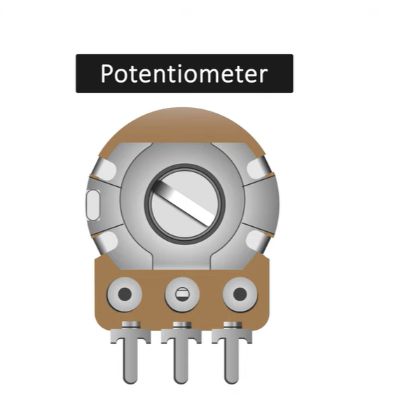
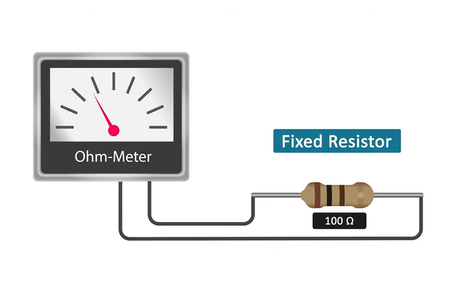
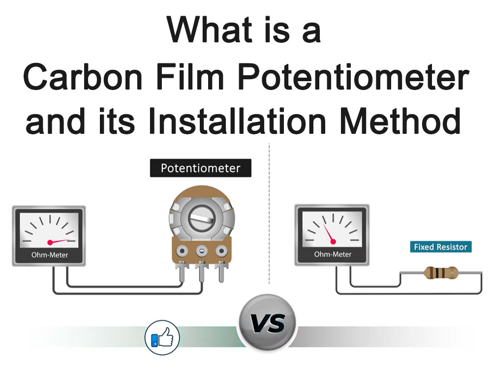
The carbon film Potentiometer is an electronic component that changes the resistance value by adjusting the length or cross-sectional area of the carbon film to achieve continuous adjustment.
It has the advantages of wide resistance range, small temperature coefficient, low noise, long life, etc., and is widely used in various electronic equipment.
What is a carbon film Potentiometer?
Carbon film Potentiometer is a common electronic component widely used in electronic equipment. Proper mounting is critical to the performance and service life of your Potentiometer.

Potentiometer Explained
What is the function of carbon film Potentiometer?
Carbon film potentiometers have many functions in electronic equipment, including regulating current and voltage, serving as rheostats, voltage dividers, and current controllers.
- Adjust current and voltage: The carbon film potentiometer can be rotated manually or adjust the resistance value of the circuit according to external control signals, thereby controlling and regulating the output of the circuit. For example, in audio circuits, it can adjust the volume; in lighting circuits, it can adjust the brightness of lights. This regulating effect makes carbon film potentiometers widely used in situations where precise control of current and voltage is required.
- Used as a rheostat: The carbon film potentiometer can be connected as a two-terminal device to obtain a smoothly and continuously changing resistance value within the stroke range of the slide potentiometer. This property allows the carbon film potentiometer to be used as a rheostat.
- Use as a voltage divider: The carbon film potentiometer is a continuously adjustable resistor. When the rotating handle or sliding handle of the potentiometer is adjusted, the movable contact slides on the resistor body. At this time, an output voltage that is related to the applied voltage of the potentiometer and the angle or stroke of the movable arm can be obtained at the output end of the potentiometer. Therefore, a carbon film potentiometer can be used as a voltage divider.
- Use as a current controller: When the carbon film potentiometer is used as a current controller, one of the selected current output terminals must be the sliding contact terminal. By adjusting the resistance value of the carbon film potentiometer, the current in the circuit can be controlled.
- Fine-tune bias and gain, set LCD contrast, adjust power supply voltage, etc.: Since the resistance value of the carbon film potentiometer is adjustable, it also has certain applications in fine-tuning bias and gain, setting LCD contrast, adjusting power supply voltage, etc. .
In general, the application of carbon film potentiometer is very wide, and its regulating effect makes it widely used in various electronic equipment.
Carbon film Potentiometer advantages and disadvantages
The carbon film Potentiometer is a commonly used electronic component that has some significant advantages and disadvantages.

Advantage:
Low price:
The manufacturing cost of carbon film Potentiometers is relatively low, so they are relatively cheap and suitable for large-scale applications.
Small size:
The carbon film Potentiometer is small in size, suitable for use in limited spaces, and can be easily integrated into various electronic devices.
Good resistance stability:
Due to the stable conductivity of the carbon film, the carbon film Potentiometer has good resistance stability and can provide stable resistance value within a certain range.
Wide adjustment range:
The carbon film potentiometer can adjust the resistance value within a wide range and can meet the needs of different circuits.
Long life, high resolution, and good wear resistance:
This is also one of the reasons why carbon film Potentiometers are widely accepted in practical applications.
Disadvantages:
Nonlinearity:
There is a certain nonlinear relationship between the resistance value of the carbon film Potentiometer and the position of the sliding contact, which may cause problems in some precision applications.
Weak moisture resistance:
The moisture resistance of carbon film Potentiometers is relatively weak, and it is easy to get damp in humid environments, resulting in performance degradation or damage.
Large current noise:
Carbon film Potentiometers will produce large current noise when working, which may affect the performance and stability of the circuit.
Poor resistance stability:
Although the carbon film Potentiometer has good resistance stability overall, under certain circumstances, its resistance value may change, resulting in unstable circuit performance.
Please note that these are just some common advantages and disadvantages of carbon film potentiometers, and actual applications may vary depending on the specific model and usage conditions. When selecting a potentiometer, it is recommended to consider comprehensively based on specific needs and application scenarios.
Carbon film potentiometer application fields
Carbon film potentiometers are widely used in various fields. The following are some of their application fields:
- Electronic equipment: used to control volume, screen brightness, power voltage, etc.
- Communication equipment: used to adjust signal strength, frequency, etc.
- Instruments: used to measure and adjust various physical quantities, such as temperature, pressure, flow, etc.
- Audio equipment: used to adjust the volume, balance, etc. of audio signals.
- Automotive electronics: Used to adjust various parameters of automotive electronic equipment, such as car light brightness, seat position, etc.
- Aerospace: Used to adjust various parameters of the aircraft, such as flight attitude, navigation signals, etc.
The application fields of carbon film potentiometers are very wide, and different types of carbon film potentiometers can be selected according to different needs.
Carbon film Potentiometer FAQs
Common faults of carbon film Potentiometers include loud rotational noise, internal circuit breakage of pins, resistor body wear, burnout, switch damage, etc.
- Loud rotating noise: mainly occurs in the volume potentiometer, because the volume potentiometer rotates frequently. Generally, volume potentiometers or tone potentiometers will more or less suffer from loud rotational noise after being used for a period of time. This is mainly due to the friction between the moving piece contacts and the carbon film, causing damage to the carbon film, causing the moving piece to be in contact with the carbon film. Poor contact between membranes.
- Internal break in the pin: When the pin of the carbon film potentiometer is broken internally, the carbon film potentiometer will not work, that is, there will be no change in the current or voltage of the circuit when the shaft is rotated. For the volume carbon film potentiometer, there may be a silent failure or the volume will not turn off.
- Resistor body wear and burnout: The resistor body can also be severely burned due to overcurrent, causing an open circuit. For carbon film potentiometers whose pins are internally broken or the resistor is burned out and open circuited, it is generally inconvenient to repair them and must be replaced.
In addition, the wear of the carbon film potentiometer will also lead to poor contact between the contacts and the carbon diaphragm, causing noise or unstable volume.
What is the difference between a carbon film potentiometer and an ordinary potentiometer?
There are certain differences in structure and application between carbon film potentiometers and ordinary potentiometers.
Structure
- Carbon film potentiometer: Made of carbon layer material, usually graphite or carbon black is infiltrated into an amorphous matrix, and a carbon film is formed through high temperature treatment. The resistance value of the carbon film potentiometer can be adjusted by the position of the sliding contact.
- Ordinary potentiometer: It is usually composed of a resistance wire wound on a grooved insulator. One end of the resistance wire is fixed on the center stake, and the other end is connected to the sliding contact arm. Adjusting the position of the contact arm can change the length of the resistance wire, thereby changing the resistance value.
Application
- Carbon film potentiometer: Due to its stable resistance, low noise, long life, and good wear resistance, it is widely used in various electronic equipment, such as radios, tape recorders, televisions, etc.
- Ordinary potentiometer: usually used in situations where current or voltage needs to be adjusted, such as power circuits, audio circuits, etc.
Advantages and Disadvantages
- Carbon film potentiometer: simple structure, low noise, good wear resistance, long life and high stability. However, its resistance range is smaller and its adjustment accuracy is not as good as that of ordinary potentiometers.
- Ordinary potentiometer: high adjustment accuracy and wide resistance range. However, its structure is complex, noise is loud, wear resistance is poor, and life is short.
In summary, carbon film potentiometers and ordinary potentiometers are different in structure and application.
The choice of which Potentiometer to use should be determined based on specific application needs and circuit requirements.
Carbon film Potentiometer installation methods and precautions
This article will introduce the installation methods and precautions of carbon film Potentiometers to help readers install and use carbon film Potentiometers correctly.
Installation method
- Determine the installation location: Before installing the carbon film Potentiometer, you need to determine the installation location. According to the circuit design and equipment requirements, select the appropriate location for installation.
- Clean the installation area: Before installation, make sure the installation area is clean and dust-free. Use a cleaning cloth or cotton swab to remove dust and debris so as not to affect the normal operation of the potentiometer.
- Determine the pin direction: Carbon film potentiometers usually have three pins, one of which is the middle pin and the other two are on both sides. Determine the direction of the pins based on the circuit diagram or device manual.
- Connect the circuit: Connect the pins of the potentiometer to the pads on the circuit board. Use soldering tin and a soldering station to make sure the welding is firm and reliable.
- Adjust the position of the potentiometer: After the installation is completed, the position of the potentiometer can be adjusted as needed. By rotating the potentiometer, the resistance value can be changed to adjust the working state of the circuit.
Precautions
- Prevent static electricity: Before installing the carbon film potentiometer, attention should be paid to preventing the generation of static electricity. Static electricity may damage the internal structure of the potentiometer and affect its performance. During operation, anti-static gloves or anti-static mats can be used to reduce the generation of static electricity.
- Avoid excessive force: During installation, avoid using excessive force. Excessive force may cause the potentiometer’s pins to bend or break, affecting its normal operation.
- Avoid overheating: During the welding process, care should be taken to avoid overheating. Excessively high temperatures may damage the internal structure of the potentiometer, causing performance degradation or failure. Use appropriate welding temperature and time to ensure welding quality.
- Prevent contamination: During the installation process, avoid contact between the carbon film potentiometer and oil, moisture and other substances. These substances may cause corrosion or short circuit of the potentiometer, affecting its normal operation.
- Pay attention to circuit connection: When connecting the circuit, make sure that the pins and pads are connected correctly. Incorrect connections may cause circuit failure or damage to the potentiometer.
Proper installation is critical to the performance and service life of carbon film potentiometers. When installing a carbon film potentiometer, you should pay attention to cleaning the installation area, preventing static electricity, avoiding excessive force and overheating, preventing contamination, and paying attention to the correct connection of the circuit.
By following these precautions, you can ensure the proper operation and long-term use of your carbon film potentiometer.
Question 2 Answer
There are three types of relationships between the resistance change of the carbon film potentiometer and the position of the middle contact: linear, logarithmic and exponential.
The advantage is that the resistor is made of ground carbon black, graphite, quartz and other materials coated on the surface of the substrate. The process is simple and it is currently the most widely used potentiometer. It is characterized by high resolution, good wear resistance and long life. The disadvantages are large current noise, large nonlinearity, poor moisture resistance and resistance stability.
The fault characteristics of carbon film potentiometers can be mainly divided into three categories, namely internal pin open circuit faults, severe burnout faults due to overcurrent, and high rotational noise.
Since the metallic glass glaze is sintered at high temperatures, all materials are inorganic materials that are resistant to oxidation and high temperature, so they have good heat resistance.
Various trimmer Potentiometers can be installed directly on the printed circuit board, but attention should be paid to the arrangement of adjacent components to ensure that the Potentiometer is conveniently adjusted without affecting adjacent components. The carbon film Potentiometer must be secure and reliable when installed, and the nuts that should be tightened should be tightened.
The voltage drop generated when current flows through a high-resistance carbon film Potentiometer must not exceed the maximum operating voltage allowed by the Potentiometer. In order to prevent the contacts and conductive layers of the carbon film Potentiometer from deteriorating or burning, the operating current of the small resistance Potentiometer must not exceed the maximum current allowed by the contacts.

