Bipolar transistor parameter symbols and their meanings

Bipolar transistor parameter symbols and their meanings

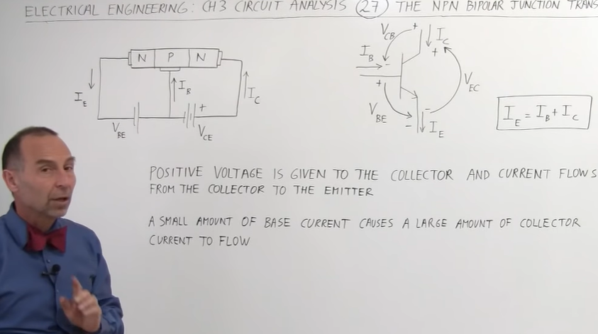
Bipolar transistors have many parameter symbols and their meanings. For example, B, C, and E represent the base, collector, and emitter respectively. Ib, Ic, and Ie represent the currents of the base, collector, and emitter, respectively, while Vcb, Vbe , Vce represents the voltage between the collector and the base, the emitter and the base, and the collector and the emitter.
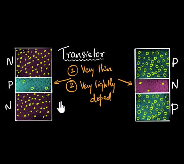
Bipolar transistor parameter meaning

Together, these parameter symbols define the operating characteristics of a bipolar transistor and are critical to understanding its performance and how it is used.

Bipolar transistor is a common electronic device. Its parameter symbols and their meanings are as follows:

  • Ic: collector current, refers to the DC current passing through the collector of the transistor under given conditions. The average value of collector DC or AC current.
  • Icbo: The reverse saturation current between the base and collector when the emitter is open circuit. The base is grounded, the emitter is open to ground, and the reverse cut-off current between the collector and the base under the specified VCB reverse voltage condition
  • Iceo: The reverse blocking current between the emitter and collector when the base is open circuit at a given temperature. The emitter is connected to ground and the base is open to ground. Under the specified reverse voltage VCE condition, the reverse cut-off current between the collector and emitter is reached.
Research and Analysis on the Working Principle of Bipolar Transistors
  • Iebo: Reverse cutoff current between base and emitter when collector is open circuit at a given temperature. The base is grounded, the collector is open to ground, and under the specified reverse voltage VEB condition, the reverse cut-off current between the emitter and the base is reached.
  • IB: The average value of base DC current or AC current
  • IE: the average value of the emitter DC current or AC current
  • Icer: The series resistor R between the base and the emitter. When the voltage VCE between the collector and the emitter is a specified value, the reverse cut-off current between the collector and the emitter is
  • Ices: The emitter is grounded, the base is short-circuited to ground, and under the specified reverse voltage VCE condition, the reverse cut-off current between the collector and the emitter
  • Icex: The emitter is grounded, a specified bias voltage is applied between the base and the emitter, and under the specified reverse bias voltage VCE, the reverse cut-off current between the collector and the emitter
  • ICM: The maximum allowable current of the collector or the maximum average value of the AC current.
  • IBM: The maximum value of DC current that can continuously pass through the base within the range that the collector is allowed to dissipate power, or the maximum average value of AC current
  • ICMP: collector maximum allowable pulse current
  • ISB: secondary breakdown current
  • IAGC: forward automatic current control
  • Pc: collector dissipation power, which refers to the maximum power that the transistor can withstand during normal operation.
  • PCM: The maximum allowable power dissipation of the collector refers to the maximum power dissipation that the transistor can withstand under given conditions.
  • Pi: input power
  • Po: output power
  • Posc: oscillation power
  • Pn: noise power
  • Ptot: total power dissipated
  • VCB: Reverse breakdown voltage between collector and base.
  • VBE (Vb): forward voltage between base and emitter.
  • VCEO: Reverse breakdown voltage between collector and emitter.
  • VCES: Saturation voltage between collector and emitter.
  • β: Common base amplification factor, which refers to the ratio of the change of the output signal to the change of the input signal in the common base circuit.
  • α: Common emitter amplification factor, which refers to the ratio of the change amount of the output signal to the change amount of the input signal in the common emitter circuit.
  • fT: Characteristic frequency of the transistor, which refers to the highest operating frequency of the transistor.
  • fmax: The limit frequency of the transistor, which refers to the highest frequency at which the transistor can operate normally. The operating frequency when the triode power gain is equal to 1.
  • fmin: The lowest operating frequency of the transistor, which refers to the lowest frequency at which the transistor can operate normally.
  • fα: Common emitter cutoff frequency, which refers to the frequency point at which the amplification factor begins to decrease when the frequency of the input signal increases in the common emitter circuit.
  • fβ: The turning frequency of the frequency response of the common emitter signal source, which refers to the frequency point at which the amplification factor begins to decrease when the frequency of the input signal increases in the common emitter circuit.
  • fH: Common base cutoff frequency, which refers to the frequency point at which the amplification factor begins to decrease when the frequency of the input signal increases in the common base circuit.
  • fL: The turning frequency of the frequency response of the common base signal source, which refers to the frequency point at which the amplification factor begins to decrease when the frequency of the input signal increases in the common base circuit.
  • Vf: forward voltage drop, refers to the forward conduction voltage of the transistor.
  • Vr: Reverse voltage drop, refers to the reverse conduction voltage of the transistor.
  • VCB: collector-base (DC) voltage
  • VCE: collector-emitter (DC) voltage
  • VBE: Base-emitter (DC) voltage
BJT transistor analysis
  • VCBO: The base is grounded, the emitter is open to ground, and the maximum withstand voltage between the collector and the base under specified conditions
  • VEBO: The base is grounded, the collector is open to ground, and the maximum withstand voltage between the emitter and the base under specified conditions
  • VCEO: The emitter is grounded, the base is open to ground, and the maximum withstand voltage between the collector and emitter under specified conditions
  • VCER: The emitter is grounded, a resistor R is connected in series between the base and the emitter, and the maximum withstand voltage between the collector and the emitter under specified conditions
  • VCES: The emitter is grounded, the base is short-circuited to ground, and the maximum withstand voltage between the collector and emitter under specified conditions
  • VCEX: The emitter is grounded, a specified bias voltage is applied between the base and the emitter, and the maximum withstand voltage between the collector and the emitter under specified conditions
  • Vp: punch-through voltage.
  • VSB: Secondary breakdown voltage
  • VBB: Base (DC) power supply voltage (external circuit parameters)
  • Vcc: Collector (DC) power supply voltage (external circuit parameters)
  • VEE: Emitter (DC) power supply voltage (external circuit parameters)
  • VCE(sat): The emitter is grounded, and the saturation voltage drop between the collector and the emitter under Ic and IB conditions is specified.
  • VBE(sat): The emitter is grounded, and under specified Ic and IB conditions, the base-emitter saturation voltage drop (forward voltage drop)
  • VAGC: forward automatic gain control voltage
  • Vn(p-p): Peak equivalent noise voltage at the input end
  • V n: noise voltage
  • D: duty cycle
  • Bvceo: Reverse breakdown voltage, which refers to the maximum reverse voltage between the base and collector of a transistor during normal operation.
  • BVcbo: open emitter, breakdown voltage between collector and base
  • Bvbeo: Forward breakdown voltage refers to the maximum forward voltage between the base and emitter of a transistor during normal operation.
  • Bvces: saturation voltage drop, refers to the voltage drop between the base and emitter of the transistor when it is in saturation state. Base and emitter short circuit CE junction breakdown voltage.
  • BVebo: Open collector EB junction breakdown voltage.
  • BV cer: The base and emitter are connected in series with a resistor, CE junction breakdown voltage.
  • αF: forward current amplification factor, refers to the forward current amplification coefficient of the transistor.
  • αR: Reverse current amplification factor, which refers to the reverse current amplification coefficient of the transistor.
  • fmaxF: forward maximum operating frequency, refers to the upper limit of the forward operating frequency of the transistor.
  • fmaxR: reverse maximum operating frequency, which refers to the upper limit of the reverse operating frequency of the transistor.
  • fminF: forward minimum operating frequency, refers to the lower limit of the forward operating frequency of the transistor.
  • fminR: Reverse minimum operating frequency, which refers to the lower limit of the reverse operating voltage of the transistor.
  • Cc: collector capacitance
  • Ccb: Capacitance between collector and base
  • Cce: emitter ground output capacitance
  • Ci: input capacitance
  • Cib: common base input capacitance
  • Cie: common emitter input capacitance
  • Cies: common-emitter short-circuit input capacitance
  • Cieo: Common emitter open input capacitance
  • Cn: Neutralizing capacitor (external circuit parameters)
  • Co: zero bias capacitor
  • Cob: common base output capacitor. In the base circuit, the output capacitance between the collector and the base
  • Coe: common emitter output capacitance
  • Coeo: Common emitter open output capacitor
  • Cre: common emitter feedback capacitor
  • Cic: collector junction barrier capacitance
  • CL: Load capacitance (external circuit parameters)
  • Cp: parallel capacitance (external circuit parameters)
  • Cj: Junction (interelectrode) capacitance, indicating the total capacitance of the germanium detection diode when a specified bias voltage is applied to both ends of the diode.
  • Cjv: bias junction capacitance
  • Cjo: zero bias junction capacitance
  • Cjo/Cjn: junction capacitance change
  • Cs: case capacitance or package capacitance
  • Ct: total capacitance
  • CTV: voltage temperature coefficient. The ratio of the relative change of the stable voltage to the absolute change of the ambient temperature under the test current
  • CTC: Capacitance temperature coefficient
  • Cvn: nominal capacitance
  • hFE: common emitter quiescent current amplification factor
  • hIE: common emitter static input impedance
  • hOE: common emitter static output conductance
  • h RE: Common emitter static voltage feedback coefficient
  • hie: total emission of very small signal short-circuit input impedance
  • hre: total emission of very small signal open circuit voltage feedback coefficient
  • hfe: total emission of very small signal short-circuit voltage amplification factor
  • hoe: total emission of very small signal open circuit output admittance
  • ESB: Second breakdown energy
  • rbb: base area extended resistance (base area intrinsic resistance)
  • rbbCc: base-collector time constant, which is the product of base extension resistance and collector junction capacitance
  • rie: input resistance when the emitter is grounded and the AC output is short-circuited
  • roe: The output resistance when the emitter is grounded and the AC input is short-circuited when measured under specified VCE, Ic or IE, and frequency conditions.
  • RE: External emitter resistor (external circuit parameters)
  • RB: External base resistor (external circuit parameters)
  • Rc: external collector resistor (external circuit parameters)
  • RBE: External base-emitter resistance (external circuit parameters)
  • RL: Load resistance (external circuit parameters)
  • RG: signal source internal resistance
  • Rth: thermal resistance
  • Ta: ambient temperature
  • Tc: shell temperature
  • Ts: junction temperature
  • Tjm: maximum allowable junction temperature
  • Tstg: storage temperature
  • td: delay time
  • tr: rise time
  • ts: storage time
  • tf: fall time
  • ton: opening time
  • toff: off time
  • IF: Forward DC current (forward test current). The current passing through the inter-electrode of the germanium detection diode under the specified forward voltage VF; the maximum operating current (average value) allowed to pass continuously in the sinusoidal half-wave of the silicon rectifier and silicon stack under the specified conditions of use, and the silicon switch The maximum forward DC current allowed to pass through the diode under rated power; the current given when measuring the forward electrical parameters of the Zener diode.
  • IF (AV): forward average current
  • IFM (IM): Forward peak current (forward maximum current). The maximum forward pulse current allowed through the diode at rated power. LED limits.
What are the application scenarios of bipolar transistors?

The application scenarios of bipolar transistors mainly include the following aspects:
In the fields of radio, television, communications, radar, computers, automatic control devices, electronic instruments, household appliances, etc., used for amplification, oscillation, switching and other functions.
Traditional industries such as industry, communications, computers, consumer electronics, automotive electronics, aerospace, national defense and military industries, as well as emerging industries such as rail transit, new energy, smart grids, and new energy vehicles.
Constitute amplifier circuits, or drive speakers, motors and other equipment, and are widely used in aerospace engineering, medical equipment, robots and other application products.
As a key component of amplifiers in audio amplification, radio frequency amplification, video amplification and other fields.

What are the disadvantages of bipolar transistors?

Disadvantages of bipolar transistors include temperature sensitivity and bias, which can cause circuit instability. In addition, bipolar transistors may introduce noise that affects circuit performance. In high-speed switching circuits, the response speed of bipolar transistors is relatively slow and is not as stable as field effect transistors. In addition, bipolar transistors consume large amounts of power, require large drive currents, and are relatively large in size.
Despite these shortcomings, bipolar transistors are still used in many fields because of their advantages such as fast response speed, high amplification, and low noise. Choosing the right transistor based on specific needs can improve the performance and stability of your circuit.

What is the meaning of collector current Ic, Ice, Ie?

The collector currents Ic, Ice, and Ie have the following meanings:
Ic is the limit value, which refers to the collector current, and C represents the collector. The specific meaning of Ic is the maximum DC current of the collector.
Iceo, ICES, and ICER are called transistor collector reverse current. Their names and meanings are as follows: When the emitter is open and a reverse voltage is applied between the collector and the base, the reverse current of the collector is usually called the reverse current. towards saturation current.
Ie represents the current at the emission extreme.
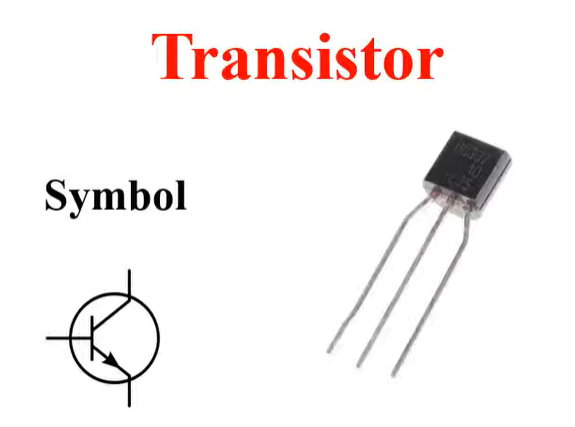
In addition, the transistor has three ports, E emitter, B base and C collector, and I represents the current, IE represents the current at the emitter terminal, IB represents the current at the base terminal, and IC represents the current at the collector terminal.

What are the applications of bipolar transistors?

Bipolar transistors have a wide range of applications, mainly including the following aspects:
Communication field: Bipolar transistors are used for signal amplification, oscillation, switching, etc., and are widely used in radio, television, communications, radar and other fields.
Industrial control field: As a key electronic device, bipolar transistors are used to realize amplification, switching, isolation and other functions of control circuits, and are widely used in industrial automation control systems.
Consumer electronics: Bipolar transistors are used in audio amplification, video amplification, switching circuits, etc., and are key components in many electronic products.
Automotive electronics: Bipolar transistors are used in automotive sensors, ignitions, lighting control and other circuits to function as signal amplification and switching.
Aerospace field: Bipolar transistors have the characteristics of high reliability and long life, and are suitable for various electronic equipment in aerospace engineering.
Medical device field: Bipolar transistors are used in sensors, amplifiers and other circuits in medical devices to perform signal processing and amplification.
Robot field: Bipolar transistors are used in robot control systems and sensor circuits to achieve signal amplification and processing.
Bipolar transistors have a wide range of applications, covering communications, industrial control, consumer electronics, automotive electronics, aerospace, medical equipment and robotics.

NPN Transistor Fabrication Steps and Chemical Analysis

NPN transistor fabrication steps and chemical analysis

NPN transistors are three-terminal semiconductor devices consisting of a base, an emitter, and a collector. It is one of the most important components in electronic circuits and is used for amplification, switching and logic operations.

The manufacturing process of NPN transistors is divided into the following steps:

Substrate selection

NPN transistor fabrication steps and chemical analysis
  1. Select the appropriate substrate material, such as silicon wafer, germanium wafer, etc., according to the specifications and application requirements of the transistor.
  2. Consider the mechanical properties, thermal stability, chemical stability and compatibility with subsequent processes of the substrate.

surface treatment

  1. Clean the substrate to remove surface impurities and contaminants.
  2. Carry out oxidation or nitriding treatment to form a protective layer and improve surface properties.

crystal growth

From sand to silicon – transistor crystal growth process – transistor chemistry research and analysis
  1. Use physical vapor deposition, chemical vapor deposition and other methods to grow single crystal materials on the selected substrate.
  2. Control parameters such as temperature, pressure, air flow, etc. to ensure the quality and stability of crystal growth.

transistor doping

  1. The required impurities are introduced into the crystal by methods such as ion implantation, diffusion or chemical vapor deposition.
  2. The purpose of doping is to form a conductive channel and control the conductive performance of the transistor.

Transistors make PN junctions

NPN transistor fabrication steps and chemical analysis
  1. Perform photolithography, etching and other processes on the crystal surface to form a PN junction structure.
  2. The PN junction is formed through heat treatment or chemical treatment.

Transistor electrode manufacturing

How to make electrodes for transistors – Electronics: NPN Transistors
  1. Make metal electrodes on the crystal surface to realize current input and output.
  2. Select appropriate metal materials and process conditions to ensure good contact between the electrode and the crystal material.

Transistor packaging testing

  1. Encapsulate the transistor in a suitable casing to protect it from the external environment.
  2. Conduct electrical performance testing to ensure the normal function and stable performance of the transistor.

Chemical analysis of NPN transistors

Ingredient analysis

  1. Determine the types and contents of various elements in the crystal through mass spectrometer (MS) or X-ray fluorescence spectrometer (XRF).
  2. Determine the distribution and concentration of impurity elements and evaluate their impact on transistor performance.

Chemical bonding state analysis

Transistor expert explains circuit analysis of transistor (NPN and PNP) circuits
  1. Use infrared spectroscopy (IR) technology to analyze the chemical bonding state in the crystal.
  2. Understand the role of different chemical bonds in crystals and their impact on transistor performance.

Surface chemical analysis

  1. Use techniques such as atomic force microscopy (AFM) and X-ray photoelectron spectroscopy (XPS) to analyze the chemical properties and element distribution on the crystal surface.
  2. Understand the presence of surface contaminants and their impact on transistor performance.

Chemical stability analysis

  1. Evaluate the stability of crystals under different temperatures and atmospheres through thermogravimetric analysis (TGA), differential thermal analysis (DSC) and other methods.
  2. Analyze the performance changes of crystals in harsh environments to provide basis for their application.
Transistor example

Comprehensive analysis methods combined with computer simulation technology

Build more accurate models to predict and optimize transistor performance.

transistors for computers - transistors symbol

Through the above introduction of manufacturing steps and chemical analysis, we can better understand the manufacturing process and performance characteristics of NPN transistors, and provide guidance for actual production and application.

Chemical analysis of NPN transistors can be used to determine their structure and composition. Commonly used analysis methods include:

Energy spectroscopy

Energy spectroscopy can be used to determine the content of elements in a transistor.

Spectroscopy

Spectroscopy can be used to determine the type and concentration of impurities in a transistor.

Electrochemical analysis

Electrochemical analysis can be used to determine the doping type and concentration of a transistor.

These analytical methods help manufacturers ensure that transistors meet required characteristics.

What instruments and equipment are needed for chemical analysis of NPN transistors?

Transistor Manufacturer Brand - Infineon

When performing chemical analysis of NPN transistors, you may need to use the following instruments and equipment:

electron microscope

Used to observe the microstructure of the crystal surface and interior.

X-ray diffractometer

It is used to determine the crystal structure and analyze the atomic spacing and relative content of various elements in the crystal.

infrared spectrometer

Used to determine chemical bonds and molecular structure in crystals.

atomic force microscope

Used to analyze the morphology and chemical properties of crystal surfaces.

mass spectrometer

Used to determine the relative content of elements in crystals.

Electronic energy spectrometer

Used to analyze the chemical state and electronic structure of crystal surface elements.

These instruments can help us deeply understand the chemical and physical properties of NPN transistors, thereby optimizing their performance and improving their reliability.

Analyze the manufacturing process of transistor manufacturers

Analyze the manufacturing process of transistor manufacturers pdf

The manufacturing process of transistor manufacturers is a highly complex and precise technology involving multiple steps, including crystal growth, wafer preparation, doping, etching, electrode fabrication and packaging.

Each step requires strict quality control and precise operations to ensure the performance and consistency of the final product. Still, transistor manufacturing faces challenges such as high material costs, difficulties with precise doping, packaging and testing challenges, and pressure to continually upgrade technology. In order to overcome these challenges, transistor manufacturers continue to strive to improve the level and technological content of manufacturing processes to provide high-quality, high-performance transistor products.

What do transistor manufacturers do?

Transistor manufacturers are manufacturers that specialize in producing transistors. Their main job is to manufacture and produce transistors to meet the needs of different electronic devices.

Transistor is a semiconductor device with high sensitivity, low noise, high reliability, stability and other characteristics. It is widely used in various electronic devices, such as televisions, computers, mobile phones, etc. With the continuous development of science and technology, there are more and more types and specifications of transistors, and their application fields are becoming more and more extensive.

The work of transistor manufacturers includes manufacturing and R&D of transistors, as well as providing technical support and after-sales services. They use advanced production processes and equipment to precisely control the material, size, shape, doping and other parameters of the transistor to ensure that its electrical characteristics and performance meet the requirements.

Analyze the manufacturing process of transistor manufacturers

In addition to manufacturing transistors, some transistor manufacturers also provide customization services, designing and producing specific transistors based on customer needs and specifications.

Transistor manufacturers are manufacturers that specialize in the production of transistors. They are committed to providing high-quality, high-performance transistor products to meet the needs of different applications.

Why do transistor manufacturers make transistors?

Transistor manufacturers make transistors for the following reasons:

Achieve miniaturization and efficiency

A transistor is a semiconductor device whose size and shape affect its electrical properties. By precisely controlling the size and shape of transistors, more efficient and smaller electronic devices can be achieved.

Improve equipment reliability and stability

Transistors have high reliability and stability, which allows them to function well in a variety of environments. Transistors are very important components for some devices that require long-term operation or high-precision control.

Achieve high sensitivity and low noise performance

The transistor has high sensitivity and low noise performance, can operate normally in a weak signal environment, and can also achieve high-precision signal processing.

Meet different application needs

There are many types and specifications of transistors to meet the needs of different applications. For example, some special types of transistors can be used to operate in high power, high frequency, or high temperature environments.

Achieve mass production

With the development of semiconductor technology, the production of transistors has achieved large-scale production, which makes their prices relatively low and also laid the foundation for the popularization of electronic devices.
The transistor is an important semiconductor device with many advantages and uses. Therefore, transistor manufacturers are committed to manufacturing and developing transistors to meet the needs of different applications.

Why do transistor manufacturers make transistors?

What is the manufacturing process of transistor manufacturers?

The manufacturing process of transistor manufacturers includes multiple steps. The following is a detailed description:

crystal growth

This is the first step in making a transistor, whose core component is a semiconductor material, usually silicon. High-purity silicon material is heated and melted, and then the conductive properties of the crystal are controlled by introducing impurity atoms to obtain single-crystal silicon rods with specific properties. This process can use a variety of methods, including the Czochralski method, zone melting method, floating zone method, etc.

Wafer preparation

Wafers are the basis for transistor production, usually using monocrystalline silicon or polycrystalline silicon materials. The silicon material is subjected to multiple high-temperature treatments to turn it into pure polysilicon rods, which are then sawed into thin slices to form 8-inch diameter discs, known as wafers.

Doping

The purpose of doping is to change certain properties of the material by adding other elements without changing the basic chemical structure of the material. During the fabrication of transistors, doping helps control their conductive properties.

butterfly etching

Butterfly etching is a common etching technology during transistor manufacturing. With this technique, specific shapes and sizes can be carved into silicon wafers to achieve precise control of electrical current.

Electrode production

One of the key parts of a transistor is the electrode, which is used to guide the flow of electricity. During the manufacturing process, electrodes need to be accurately formed on the silicon wafer and ensure good contact between the electrodes and the semiconductor material.

transistor package

Finally, transistors need to be packaged to protect their internal semiconductor materials and electrodes. Packaging protects the transistor from external environmental influences and also allows the transistor to be connected to external circuitry.

Challenges and difficulties in the manufacturing process of transistor manufacturers

The above are the main steps of the manufacturing process of transistor manufacturers and are also the key steps of the transistor manufacturing process. It should be noted that the equipment and materials used in different process steps may be different, and the specific manufacturing process will also vary depending on the manufacturer and product type.

Challenges and difficulties in the manufacturing process of transistor manufacturers

The challenges and difficulties faced by transistor manufacturers in the manufacturing process mainly include the following aspects:

Process complexity

The manufacturing process of transistors is very complex and requires precise control of every production link. For example, when manufacturing transistors, it is necessary to precisely control the purity, thickness, doping and other parameters of the material to ensure that its electrical characteristics and performance meet the requirements. In addition, high-precision manufacturing equipment and technology are also required to ensure that the manufactured transistors have high precision, high consistency, and high stability.

High cost of materials

Transistor manufacturing requires the use of a variety of high-purity, high-precision materials, such as monocrystalline silicon, silicon oxide, polycrystalline silicon, gallium arsenic, etc. These materials are more expensive, and some materials are more difficult to produce and process, resulting in higher manufacturing costs for transistors.

The challenge of precision doping

Doping is one of the important links in transistor manufacturing, which directly affects the electrical characteristics and performance of the transistor. However, controlling the accuracy and consistency of doping is difficult and requires the use of advanced equipment and manufacturing techniques.

Packaging and testing challenges

After the transistor is manufactured, it needs to be packaged and tested. In this link, it is necessary to ensure the safety and stability of the transistor, and at the same time ensure that its electrical characteristics and performance meet the requirements. This requires the use of high-precision test equipment and testing techniques to ensure that the quality and performance of each transistor is up to standard.

The pressure of continuous technological upgrading

With the continuous development of technology, there are more and more types and specifications of transistors, and the requirements for manufacturing processes are getting higher and higher. In order to remain competitive, transistor manufacturers need to continuously upgrade technology and equipment to meet changing market demands.

The transistor manufacturing process faces challenges such as complexity, high cost, precise doping, packaging testing and constant upgrade pressure. In order to overcome these challenges, transistor manufacturers need to continuously improve the level and technical content of their manufacturing processes to provide high-quality, high-performance transistor products.

How do transistor manufacturers overcome the challenge of high material costs?

Transistor manufacturers can take several approaches to overcome the challenge of high material costs:

Find alternative materials

Look for lower-priced, better-quality alternative materials to reduce the cost of manufacturing transistors. For example, some transistor manufacturers have begun to use compound semiconductor materials, such as gallium arsenide (GaAs), to replace traditional silicon materials.

Improve material utilization

By improving the manufacturing process and optimizing product design, the utilization rate of transistor materials is increased, waste is reduced and costs are reduced.

Achieve large-scale production

Economic benefits can be achieved by expanding production scale, increasing output and reducing unit costs.

Strengthen supply chain management

Optimize supply chain management, select reliable suppliers, and establish long-term and stable cooperative relationships to reduce material costs and procurement risks.

Carry out technology research and development and innovation

Through technological research and development and innovation, we continuously upgrade manufacturing processes and equipment to improve production efficiency and product quality, thereby reducing manufacturing costs.

Optimize product design and functionality

On the premise of meeting product performance and functional requirements, optimize product design as much as possible to reduce unnecessary material consumption and manufacturing costs.

Strengthen communication and cooperation with customers

Establish a good communication and cooperation mechanism with customers, understand market demands and product applications, and jointly promote the development and application of transistor manufacturing technology.

How do transistor manufacturers overcome the challenge of high material costs?

Transistor manufacturers need to take a variety of measures to overcome the challenge of high material costs, including finding alternative materials, improving material utilization, achieving large-scale production, strengthening supply chain management, carrying out technology research and development and innovation, optimizing product design and functions, and strengthening communication with Customer communication and cooperation, etc. These measures help reduce the manufacturing cost of transistors and improve product competitiveness and market share.

Precautions for manufacturing transistor manufacturers

Transistor manufacturers need to pay attention to the following matters during the manufacturing process:

material selection

Selecting the appropriate semiconductor material, such as silicon (Si) or compound semiconductor material, has an important impact on the performance of the transistor.

cleanse and purify

Before manufacturing, the processing environment needs to be cleaned and purified to avoid dust, impurities, etc. from affecting the quality of the transistors.

Control size and shape

The size and shape of transistors are precisely controlled to ensure their electrical characteristics and performance meet requirements.

Doping and diffusion

The conductive properties of semiconductor materials are changed through doping and diffusion technologies to form P-type and N-type regions in electronic devices, thereby realizing the working principle of transistors.

Operating frequency and switching status

The transistor must work in a switching state, and the operating frequency must be less than the cut-off frequency of the transistor to ensure its normal operation and stability.

Withstand voltage and current requirements

The withstand voltage is 2 to 3 times greater than the maximum operating voltage, and the current value is greater than 2 times the operating current to ensure the safety and reliability of the transistor during use.

Packaging and testing

After the transistor is manufactured, it needs to be packaged and tested. In this link, it is necessary to ensure the safety and stability of the transistor, and at the same time ensure that its electrical characteristics and performance meet the requirements.

Technology upgrading and research and development

With the continuous development of science and technology and changes in market demand, transistor manufacturers need to continuously upgrade technology and equipment, conduct research and development and innovation to meet the changing market demand and improve the competitiveness of their products.

Technology upgrading and research and development

There are many aspects that need to be paid attention to during the transistor manufacturing process to ensure that the manufactured transistors have high quality, high performance and reliability to meet the needs of different applications.

What chemicals do transistor manufacturers use?

The chemical materials used by transistor manufacturers mainly include semiconductor materials and auxiliary materials.

Semiconductor materials are the core raw materials for making transistors, and commonly used materials include silicon (Si) and germanium (Ge). These materials have special conductive properties and can realize the production of PN junctions and switches of transistors by controlling parameters such as impurity content and material purity.

In addition to semiconductor materials, transistor manufacturers also use some auxiliary materials, which are used to make transistor electrodes, insulating layers, and heat sinks. Common auxiliary materials include metal materials, insulation materials, thermal conductive materials, etc.

Metal materials are mainly used to make the electrodes of transistors, such as aluminum (Al), copper (Cu), gold (Au), and silver (Ag). These metal materials have excellent electrical conductivity, can provide good electrical contact, and can also be used as part of the heat sink.

Do transistor manufacturers offer custom transistors?

Insulating materials are mainly used to make the insulating layer of transistors, such as silicon dioxide (SiO2), silicon nitride (Si3N4), etc. These materials have high insulating properties and can effectively isolate the electrical contact between the transistor and other electronic components, ensuring the stability and reliability of the transistor.

Thermal conductive materials are mainly used to make heat sinks for transistors, such as copper substrates, aluminum substrates, etc. These materials have excellent thermal conductivity and can quickly dissipate the heat generated by the transistor to ensure the stability and reliability of the transistor.

It should be noted that different transistor materials have different chemical and physical properties. Therefore, transistor manufacturers need to consider the characteristics and application range of different materials when selecting materials to ensure that the manufactured transistors have high quality, high performance and reliability. Features. At the same time, since these chemical materials may have an impact on the environment and human body, corresponding safety and environmental protection measures need to be taken during use.

Do transistor manufacturers offer custom transistors?

Yes, many transistor manufacturers offer custom transistor services. These manufacturers can design and produce specific transistors based on customer needs and specifications.

In terms of custom transistors, manufacturers usually communicate and cooperate closely with customers to understand their needs and requirements, and then design and produce according to their requirements. Some manufacturers also provide comprehensive technical support and after-sales service to ensure that customers receive transistors that meet their specific needs.

Transistor manufacturer in China - SPTECH transistor Inkjet printer inverter 2SC4552 transistor factory in stock - original NPN transistor

It should be noted that customizing transistors usually requires a certain production cycle and cost, so customers need to plan their needs in advance and fully communicate and negotiate with manufacturers to ensure that they can obtain transistors that meet their needs on time.

What is an MPSA92A transistor arduino?

MPSA92 transistor application case

MPSA92 transistor arduino refers to an application method that uses A92 transistor combined with Arduino. Arduino is an open source microcontroller development board that can be used for a variety of electronic project development. By connecting the A92 transistor with Arduino, you can expand the functionality of Arduino and achieve more complex circuit designs and applications.

The A92 transistor is an NPN-type low-power transistor with high current amplification and low noise. By combining it with Arduino, you can implement signal amplification, switching, buffering, current limiting and other functions on the digital and analog input and output pins of Arduino.

By using the A92 transistor arduino, audio amplification, motor driving, photoelectric detection, temperature control and other applications can be easily realized. At the same time, due to the open source and scalability of Arduino, circuit design and program development can be easily carried out to realize various applications.

It should be noted that different application scenarios have different parameters and performance requirements for A92 transistors and Arduino. Therefore, it is necessary to select the appropriate model and specifications according to the specific application scenarios, and carry out reasonable circuit design and programming.

Are A92 and MPSA92 the same?

Yes, A92 and MPSA92 are the same. MPSA92 is a high back-voltage transistor produced by an American company, with a withstand voltage of up to 300V. MPSA92 is usually used as a complementary tube with MPSA42 transistor with opposite conduction polarity. And A92 is just a simplified name for MPSA92.

What does MPSA92 transistor equivalent or A92 transistor equivalent mean?

A92 transistor equivalence means that the A92 transistor is equivalent to other transistors in terms of circuit function. In other words, the A92 transistor can be replaced with another type of transistor without affecting the functionality of the circuit. Such equivalent transistors often come in different models and specifications, but they are used in the same way in circuits.

What is an MPSA92A transistor arduino?

What other transistor models are equivalent to the A92?

In addition to A92 transistors, there are other types of transistors that can be used equivalently to A92. For example, common TO-92 packaged transistor models include A72, A81, A41, etc. They are also NPN type low-power transistors with similar technical parameters and Performance characteristics, can be used as a replacement for A92.

It should be noted that different transistor models may have slight differences in specific applications, so the following points need to be noted when using them instead:

  1. The parameters and performance of the transistor should be as consistent or similar as possible to A92 to ensure the performance and stability of the circuit.
  2. The packaging form and pin arrangement of the transistor should be the same or similar to A92 to ensure the correctness and reliability of the circuit connection.
  3. When using new transistor models, sufficient testing and verification are required to ensure that their performance and reliability meet application requirements.

In short, when choosing a transistor model to replace A92, it is necessary to comprehensively consider various factors such as its performance, packaging form, parameters, etc., to ensure that it can work correctly and reliably.

What does MPSA92 transistor equivalent or A92 transistor equivalent mean?

A92 transistor uses

The A92 transistor is a bipolar junction transistor designed for high voltage based applications. Therefore, it is usually used in high voltage or high power circuits, such as power electronic equipment, power circuits, motor drives, etc.

It should be noted that different transistor models and specifications have different characteristics and uses. Therefore, when using transistors, you need to select the appropriate model and specifications according to the specific application scenarios and circuit requirements, and follow the technical manuals and guidelines provided by the manufacturer. Foot alignment for proper connection and application.

Hopefully this information will help you understand what the A92 transistor is used for. If you have any further questions or need further assistance, please feel free to let me know.

How is the A92 transistor different from other transistors?

The main difference between the A92 transistor and other transistors is its structure, current amplification factor and power capacity. The A92 transistor is an NPN-type low-power transistor with high current amplification and low noise. In contrast, other transistors may have different types, structures, current amplification, and power capabilities.

In addition, the A92 transistor also has a self-shutoff function and is a current-controlled bipolar, double-junction, high-power, high-backpressure power electronic device. It not only has the inherent characteristics of reduced transistor saturation voltage, short switching time and wide safe operating area, but also has greater power capacity. These characteristics give the A92 transistor an advantage over other transistors in certain applications.

How is the A92 transistor different from other transistors?

It should be noted that different types of transistors have different characteristics and uses, and appropriate models and specifications need to be selected according to specific application scenarios and circuit requirements. At the same time, when using transistors, it is also necessary to make correct connections and applications in accordance with the technical manual and pinout provided by the manufacturer.

Where can I find the A92 transistor datasheet?

The datasheet for the A92 transistor can be found on the manufacturer’s official website or on the website of the electronic component seller. Because the A92 transistor is a specific model of transistor, you need to search for the specific manufacturer or seller to obtain relevant data sheets and other technical information.

Some common electronic component sellers and manufacturers include: Arrow Electronics, Mouser Electronics, Digi-Key, Fairchild Semiconductor, NXP Semiconductors, etc. These companies often provide online databases or websites where datasheets and other related information for the A92 transistor can be found by searching or browsing product catalogs.

In addition, the data sheet of the A92 transistor can also be searched through a search engine or professional website. When searching, you can try different keywords and combinations to get more accurate search results.

What are the ways to obtain the A92 transistor data sheet?

There are several ways to obtain the A92 transistor data sheet:

  1. Manufacturer’s website: Visit the manufacturer’s website for the A92 transistor. You can usually find the relevant datasheet on the product page or datasheet. Manufacturers provide current and accurate product specifications, performance parameters and other relevant information.
  2. Electronic components database: Through the electronic components database, you can search and find the data sheet of the A92 transistor. These databases are usually maintained by professional electronic component information providers and provide detailed specifications and parameters of various components.
  3. Component Manual: In some cases, the specifications and parameters of the A92 transistor may be listed in the component manual. These manuals are usually provided by the manufacturer and contain detailed information about specific components.
  4. Professional websites and forums: Visit websites or forums dedicated to discussing electronic components. Users or experts may provide data sheets or other related information for the A92 transistor. These websites and forums often have a wealth of resources, including datasheets, specifications, and technical documentation.
  5. Authorized distributor: Contact an authorized distributor or electronic component dealer. They may provide data sheets for A92 transistors or help you find relevant information. These distributors often maintain close ties with manufacturers and are able to provide the latest product specifications and parameters.

Please note, make sure you obtain the datasheet for your A92 transistor from a reliable source to ensure accuracy, completeness, and suitability.

What parameters does the A92 transistor data sheet contain?

The A92 transistor datasheet contains the following parameters:

  1. Type: A92 transistor is an NPN type low power transistor.
  2. Maximum withstand voltage of collector and base (VCBO): 300 V.
  3. Maximum withstand voltage of collector and emitter (VCEO): 300 V.
  4. Maximum withstand voltage of emitter and base (VEBO): 5 V.
  5. Collector current (IC): Under certain conditions, the collector current of the A92 transistor can reach 500mA.
  6. DC gain: Under certain conditions, the DC gain of the A92 transistor can reach 40.
  7. Conversion frequency: Under certain conditions, the conversion frequency of the A92 transistor can reach 50MHz.
  8. Maximum collector current range: Depending on the specific specifications, the maximum collector current range of the A92 transistor may be between 200mA and 500mA.
  9. Maximum operating temperature range: The maximum operating temperature range of the A92 transistor is between -55°C and +150°C.

The above are some of the main parameters usually included in A92 transistor datasheets. In actual use, users also need to make reasonable selection and use based on actual needs and transistor specifications.

How to use MPSA92 NPN transistor correctly?

To use the MPSA92 NPN transistor correctly, you need to pay attention to the following points:

  1. Ensure correct polarity: The electrodes of the MPSA92 transistor have clear polarity marks and should be connected correctly during installation, otherwise the circuit will not work properly or the transistor will be burned out.
  2. The control signal should be appropriate: the base current of the transistor is the key to controlling the conduction of the device. If the base current is too small, the circuit may not work properly; if the base current is too large, the transistor may be damaged. Therefore, appropriate control signals need to be selected when designing the circuit.
  3. Set the working point reasonably: The working point of the transistor (ie, collector voltage and current value) is the key to affecting the performance of the device and needs to be set reasonably according to the circuit requirements and transistor characteristics.
  4. Overloading should be avoided: When a transistor is subjected to excessive current or voltage, it is easily damaged, so overloading should be avoided during use.

What other applications are there for the A92 transistor?

A92 transistors have a wide range of application scenarios. In addition to the previously mentioned applications in bus MCU motor controllers, they can also be used in the following fields:

  1. Industrial automation: A92 transistors can be used in sensors, actuators and control circuits in industrial automation systems to realize automated control of production lines and production equipment.
  2. Smart home: A92 transistors can be used in lighting, security, environmental control, etc. in smart home systems to achieve intelligent management of the home environment.
  3. Automotive electronics: A92 transistors can be used in ignition, sensing, driving, etc. in automotive electronic systems to control and manage various functions of the car.
  4. Communication equipment: A92 transistors can be used in amplification, switching, filtering, etc. in communication equipment to process and transmit signals.

In short, A92 transistors have a wide range of application scenarios and can be selected and applied according to specific needs and circuit requirements.

How are A92 transistors used in high power circuits?

The A92 transistor is an NPN type low-power transistor, which is usually used in drive and control links in high-power circuits. In high-power application scenarios such as bus MCU motor controllers, the role of the A92 transistor is to control the operation of the motor, and control the motor speed and torque by adjusting the input current and voltage of the motor.

In high-power circuits, the A92 transistor is connected between the power supply and the motor. By controlling the on and off of the transistor, the flow direction and size of the current are controlled, thereby controlling the motor. Since the A92 transistor has a high current amplification factor and low on-resistance, it can effectively improve the current driving capability while reducing energy loss in high-power circuits.

How are A92 transistors used in high power circuits?

In high-power circuit design, you need to pay attention to the following points when using A92 transistors:

  1. Heat dissipation design: A large amount of heat will be generated in high-power circuits, so effective heat dissipation design is required for the A92 transistor to avoid overheating damage. Heat sinks, air cooling, etc. can be used for heat dissipation.
  2. Power supply design: The power supply voltage and current in high-power circuits are relatively large, so the stability and reliability of the power supply need to be designed to ensure the stability and reliability of the power supply.
  3. Protection circuit design: Protection circuit design is required in high-power circuits to avoid damage to the A92 transistor and the entire circuit due to abnormal conditions such as overcurrent and overvoltage. Devices such as fuses and protection ICs can be used for protection.
MPSA92 transistor application case

A92 transistors are widely used in high-power circuits, and the performance and reliability of the entire circuit can be improved through reasonable circuit design and protection measures.

MPSA92 transistor application case

MPSA92 transistors are mainly used in high-voltage circuits, such as circuits below 300V. In addition, it is also suitable for a variety of application scenarios, such as preamplifiers, mid- and low-frequency oscillation circuits, low-power electronic switches, level conversion, etc.

The following is an application case of MPSA92 transistor:

In a motor drive circuit, MPSA92 transistors are used as switching elements. This circuit controls the on and off of the transistor through the base of the transistor, thereby controlling the rotation of the motor. In this application, the MPSA92 transistor has the advantages of low on-resistance, low saturation voltage drop and high withstand voltage capability, making the motor drive circuit more efficient and reliable.

In addition, MPSA92 transistors can also be used in audio amplifier circuits. For example, in an audio amplifier, the MPSA92 transistor is used as a preamplifier to amplify the audio signal collected by a microphone or other audio input device, and then transmit it to the post-stage circuit for further processing and amplification. In this application, the low noise, high amplification and good frequency response characteristics of the MPSA92 transistor enable the audio signal to be well amplified and transmitted.

In short, the MPSA92 transistor has a wide range of applications, and appropriate circuits and parameter settings can be selected according to different application requirements.

What is the polarity of the MPSA92A transistor?

The polarity of the MPSA92A transistor is PNP type.

What is A42 transistor? A42 transistor datasheet

The A42 transistor is an NPN low-power transistor with a TO-92 package. This kind of transistor is usually used in household appliances, 3C digital and other fields.

What is the A42 transistor equivalent?

The A42 transistor is an NPN type low-power transistor, which is usually used in the drive and control links in high-power circuits. A42 transistors are widely used in motor control, power circuits, audio amplification, photoelectric control and other fields.

Compared with the A92 transistor, the current amplification factor and on-resistance of the A42 transistor are slightly different, but their equivalent application scenarios in circuit design are similar. In circuits that require the use of A92 transistors, if the parameters and performance of the A42 transistor meet the requirements, the A42 transistor can also be considered for replacement.

It should be noted that different transistor models may have slight differences in specific applications, so the following points need to be noted when using them instead:

  1. The parameters and performance of the transistor should be as consistent or similar as possible to ensure the performance and stability of the circuit.
  2. The packaging form and pin arrangement of the transistors must be the same or similar to ensure the correctness and reliability of the circuit connection.
  3. When using new transistor models, sufficient testing and verification are required to ensure that their performance and reliability meet application requirements.
What are the application areas of A42 transistor? What is the equivalent application scenario of A42 transistor in circuit design?

In short, when choosing a transistor model to replace A92, it is necessary to comprehensively consider various factors such as its performance, packaging form, parameters, etc., to ensure that it can work correctly and reliably.

What are the application areas of A42 transistor? What is the equivalent application scenario of A42 transistor in circuit design?

The A42 transistor is a high-performance triode with a wide range of applications. Here are some common application areas for A42 transistors:

  1. Audio amplifier: The A42 transistor has high current amplification and low noise characteristics, so the amplitude of the audio signal can be amplified in the audio amplifier, thereby improving the sound quality and volume.
  2. Switching circuit: Since the A42 transistor has a stable operating temperature range and high-frequency characteristics, it can achieve fast switching action and high-frequency operation in the switching circuit.
  3. Power management: A42 transistors can be used in switching power supplies, linear regulators and other applications in power circuits.
  4. Electronic computers: A42 transistors can be used in various circuit applications in computers, such as CPUs, memory, graphics cards, etc.
  5. Communication equipment: A42 transistors can be used in radio frequency amplifiers, modems and other applications in communication equipment.
  6. Other fields: In addition to the above common application fields, A42 transistors can also be used in various other fields, such as industrial control, automotive electronics, etc.

It should be noted that different application fields have different parameters and performance requirements for A42 transistors, so it is necessary to select the appropriate model and specification according to the specific application scenario.

What is A42 transistor? A42 transistor datasheet

At the same time, when using A42 transistors, it is also necessary to make correct connections and applications in accordance with the technical manual and pinout provided by the manufacturer.

What are the advantages of A42 transistors in audio amplifiers?

The A42 transistor has the following advantages in audio amplifiers:

  1. High performance: The A42 transistor has the characteristics of high current amplification, low noise, high frequency characteristics and stable operating temperature range, so it can provide high-performance amplification and audio processing capabilities in audio amplifiers.
  2. Wide frequency band: The A42 transistor has a wide frequency band and can adapt to audio signals of different frequencies, allowing the audio amplifier to adapt to different input signals and output requirements.
  3. Low distortion: A42 transistor has a low distortion rate, so the original quality of the audio signal can be maintained in the audio amplifier to avoid signal deformation and distortion.
  4. High stability: The A42 transistor has a stable operating temperature range, so it can maintain stable performance and output effects under various environmental conditions, ensuring the stability and reliability of the audio amplifier.
  5. Strong reliability: The A42 transistor is a mature device. After years of development and application, it has high reliability and stability, which can ensure the long-term stable operation of the audio amplifier.

To sum up, the A42 transistor has the advantages of high performance, wide bandwidth, low distortion, high stability and reliability in audio amplifiers, and is an excellent audio amplifier device.

What is the high current amplification factor of the A42 transistor?

The high current amplification factor of the A42 transistor depends on the specific application and circuit design. Depending on the data sheet, the high current amplification of the A42 transistor is typically between 200 and 400 times.

What are the applications of A42 transistors in switching circuits?

It should be noted that the amplification factor in actual applications may be affected by many factors, such as operating voltage, operating temperature, circuit design, etc. Therefore, in order to obtain the best amplification effect, reasonable circuit design and parameter selection need to be carried out according to specific application scenarios and circuit requirements.

What are the applications of A42 transistors in switching circuits?

The application of A42 transistors in switching circuits mainly includes the following aspects:

  1. High-speed switching: The A42 transistor has high-speed switching characteristics and can achieve switching actions at high frequencies. Therefore, it is widely used in RF and microwave switching circuits to quickly switch signal paths or implement signal routing.
  2. Signal amplification: A42 transistor can be used to amplify weak signals. By amplifying the input signal to the appropriate amplitude, the sensitivity and reliability of the switching circuit can be improved.
  3. Buffer: In switching circuits, the A42 transistor can be used as a buffer. It can effectively isolate different parts of the circuit to reduce mutual interference and influence.
  4. Current limiting: The A42 transistor can be used to limit the size of the current. By connecting it in series or parallel in a circuit, it protects the circuit from damage by overcurrent.
  5. Logic gates: A42 transistors can be used to implement the functions of logic gates. For example, it can form basic logic gates such as AND gates, OR gates, and NOT gates, as well as more complex combinational logic gates.

It should be noted that different application scenarios have different parameters and performance requirements for A42 transistors, so it is necessary to select the appropriate model and specifications according to the specific application scenarios. At the same time, when using A42 transistors, it is also necessary to make correct connections and applications in accordance with the technical manual and pinout provided by the manufacturer.

How does the high current amplification of the A42 transistor improve sound quality?

The high current amplification of the A42 transistor plays an important role in improving sound quality. In audio amplifiers, high current amplification means that the audio signal can be better amplified, thereby increasing the amplitude and volume of the audio.

When the audio signal passes through the A42 transistor, the amplitude of the audio signal is amplified accordingly due to its high current amplification factor. In this way, the dynamic range of the audio signal is wider, that is, the details and levels of the audio can be better restored. At the same time, the low-noise characteristics of the A42 transistor can also reduce noise and distortion in the audio signal, further improving the quality of the audio.

In audio amplifiers, the A42 transistor is usually used as a power amplifier to amplify the signal output from the preamplifier to drive speakers or other audio output devices. The high current amplification factor allows the A42 transistor to provide sufficient power to ensure that the audio signal can be fully driven and played.

In summary, the high current amplification of the A42 transistor can improve the performance of audio amplifiers, thereby improving sound quality and volume. At the same time, due to its low noise characteristics and stable operating temperature range, it can provide a purer and more stable audio output effect.

What is the difference between A42 transistor and other types of transistors?

The difference between A42 transistors and other types of transistors is mainly reflected in the following aspects:

  1. Type: A42 is an NPN transistor, while other models of transistors may be PNP or other types of transistors. Different types of transistors have different characteristics and uses in terms of current control, amplification, etc.
  2. Structure: The structure of the A42 transistor is relatively simple, mainly composed of collector, emitter and base. Other types of transistors may have more complex structures, such as bipolar junction transistors (BJTs) or field-effect transistors (FETs), which differ in their internal structure.
  3. Current amplification factor: The current amplification factor of the A42 transistor is relatively high, which can reach hundreds of times. Other types of transistors may have different current amplification factors, which vary according to different uses and specifications.
  4. Frequency characteristics: The A42 transistor has good frequency characteristics and can be suitable for higher frequency circuits. Other types of transistors may have different frequency characteristics and are suitable for different frequency ranges.
  5. Power capability: The power capability of the A42 transistor is relatively small and is usually used in low-power circuits. Other types of transistors may have greater power capabilities and are suitable for high-power circuits.

In short, different types of transistors have different characteristics and uses, and appropriate models and specifications need to be selected according to specific application scenarios and circuit requirements. At the same time, when using transistors, it is also necessary to make correct connections and applications in accordance with the technical manual and pinout provided by the manufacturer.

A42 transistor datasheet

Some key parameters of the A42 transistor are as follows:

Type: NPN
Maximum collector-emitter voltage VCEO: 300V
Maximum collector current Ic: 0.5A
Collector-base maximum withstand voltage VCBO: 300V
Emitter-base maximum withstand voltage VEBO: 5V
Collector-emitter saturation voltage drop VCE(sat): unknown
Characteristic frequency fT: 50MHz
Total power dissipation Ptot: 0.625W (ambient temperature Ta=25℃)
Collector-base reverse leakage current ICBO: 0.25μA
Emitter-base reverse leakage current IEBO: 0.1μA

In addition, A42 transistors are usually packaged in TO-92, which has a smaller size and weight and is easier to integrate into the circuit. It should be noted that in specific applications, appropriate transistor models should be selected according to circuit requirements, and appropriate circuit design and optimization should be performed to ensure circuit performance and reliability.

The above data is for reference only. If you need more information, it is recommended to consult the detailed data sheet or related manual of the A42 transistor.

In addition, manufacturers and suppliers of A42 transistors may provide different data sheets and specifications, so you should pay attention to verify the reliability of the data and information sources when purchasing and using them.

A42 transistor datasheet pdf download