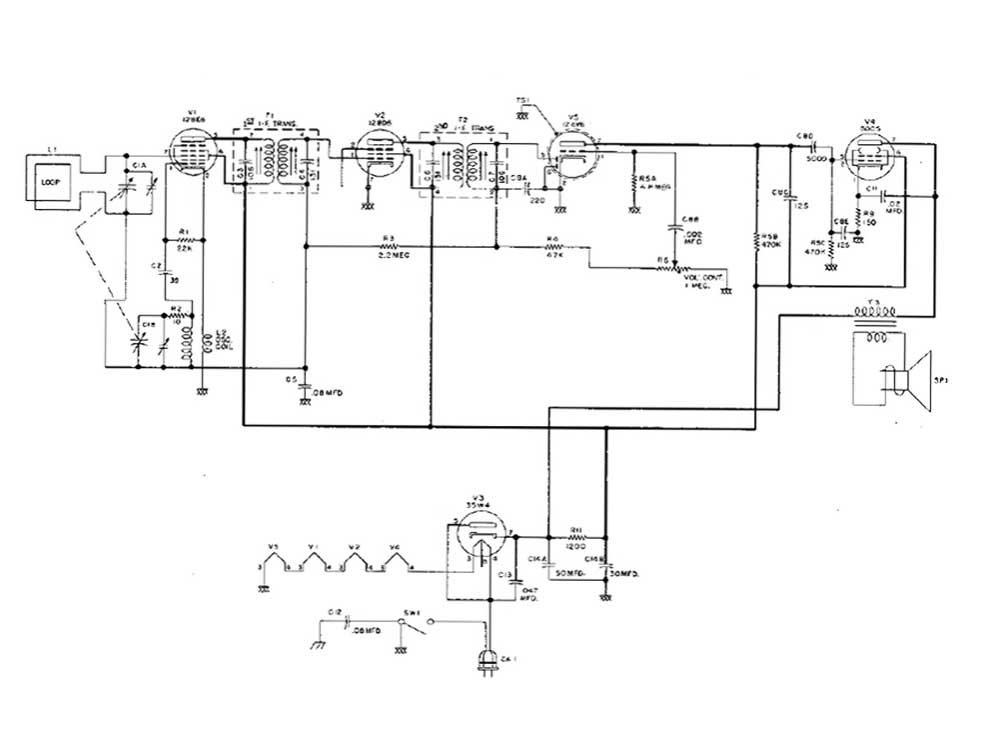
Research and analysis on the working principle of RF filter

Research and analysis on the working principle of RF filter

Radio frequency (RF) filters play a vital role in wireless communication systems. Their working principles are mainly based on the propagation characteristics of electromagnetic waves and the response characteristics of circuits.

This article will conduct an in-depth study and analysis of the working principle of RF filters, aiming to explore its performance characteristics and application scope.

Basic principles of RF filters

An RF filter is an electronic device used to filter a specific frequency range. The basic principle is to use the frequency response characteristics of the circuit to pass signals of specific frequencies through the filter while blocking signals of other frequencies. In wireless communication systems, RF filters are mainly used to filter, extract and suppress signals, thereby improving signal quality and stability.

Classification of RF filters
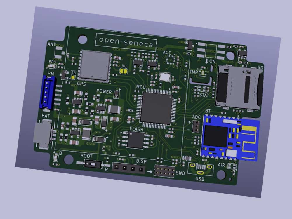
Research and analysis on the working principle of RF filter

According to different classification methods, RF filters can be divided into many types. According to the frequency response characteristics, it can be divided into low-pass filter, high-pass filter, band-pass filter and band-stop filter. According to the structural form, it can be divided into LC filters, crystal filters, ceramic filters and surface acoustic wave (SAW) filters. Each type of filter has different performance characteristics and application range.

Analysis of the working principle of RF filter

Basics of RF filters and different types of filters
  1. LC filter: The LC filter is composed of an inductor and a capacitor. By adjusting the values of the inductance and capacitance, the frequency response characteristics of the filter can be changed. When the inductor and capacitor meet certain conditions, the LC filter can achieve a band-pass or band-stop frequency response.
  2. Crystal filter: Crystal filter utilizes the piezoelectric effect of quartz crystal. By controlling the angle and vibration mode of crystal cutting, the required frequency response characteristics can be obtained. Crystal filters have high Q value and stability and are suitable for high-performance communication systems.
  3. Ceramic filter: Ceramic filter uses the dielectric constant and loss characteristics of ceramic materials. By controlling the shape and size of ceramic materials, the required frequency response characteristics can be obtained. Ceramic filters have the advantages of small size and low cost, and are widely used in fields such as mobile communications and satellite communications.
  4. SAW filter: SAW filter takes advantage of the propagation characteristics of sound waves on solid surfaces and can control sound waves by creating specific patterns on the surface of piezoelectric materials. SAW filters have the advantages of high Q value, low insertion loss and easy integration, and are widely used in the field of wireless communications.

RF filter performance parameters

  1. Cutoff frequency: refers to the frequency point at which the filter begins to suppress signals above or below a specific frequency.
  2. Bandwidth: refers to the frequency range of signals that the filter can pass.
  3. Insertion loss: refers to the degree of attenuation of the signal after the filter is connected to the circuit.
  4. Return loss: refers to the power loss caused by signal reflection.
  5. Q value: refers to the quality factor of the filter, which reflects the frequency selectivity and bandwidth of the filter.
https://www.youtube.com/watch?v=1sq8Cvju2Oo
Practical RF Filter Design and Construction

Application scenarios of RF filters

Practical RF Filter Design and Construction
  1. Mobile communications: Base stations and terminal equipment in mobile communications systems need to use high-performance RF filters to ensure signal transmission quality and stability.
  2. Satellite communications: Ground stations and satellite transponders in satellite communications systems need to use high-performance RF filters to filter and extract signals.
  3. Radar system: The transmitter and receiver in the radar system need to use high-performance RF filters to improve the radar’s resolution and anti-interference ability.
  4. Electronic warfare system: The signal processing equipment in the electronic warfare system requires the use of high-performance RF filters to identify and classify signals.
  5. Measuring instruments: The signal conditioning circuit in the measuring instruments requires the use of high-performance RF filters to improve measurement accuracy and stability.

Common RF Filter Technologies [ YouTube video tutorial]

Common RF Filter Technologies

Above, RF technology experts explain common RF filter technologies in the form of videos.

Basics of RF filters and different types of filters [ YouTube video tutorial ]

Basics of RF filters and different types of filters

The basic knowledge of RF filters and different types of filters mainly explains RF filters, the purpose of using RF filters, low-pass filters, band-pass, band-pass filters and other knowledge points.

RF filter analysis summary

As a key component in wireless communication systems, RF filters are very important in terms of their working principles and application scenarios.

This article conducts in-depth research and analysis on the basic principles, classification, working principle analysis, performance parameters and application scenarios of RF filters.

With the continuous development of wireless communication technology, the performance requirements for RF filters are becoming higher and higher.

Therefore, new high-performance RF filters need to be continuously researched and developed to meet the growing demand.

What is the principle of RF filter?

The working principle of RF filters is based on the frequency characteristics of the signal and the frequency selectivity of the filter. By designing appropriate circuit structure and parameters, RF filters can allow signals in a specific frequency range to pass while suppressing or blocking signals in other frequency ranges. In this way, useless signals can be filtered out and the purity and reliability of the signal can be improved. In a word, an RF filter is an electronic component used to achieve signal frequency selection. By changing the frequency characteristics of the filter, the frequency characteristics of the signal are changed, thereby achieving signal extraction or suppression.

What is an RF filter?

RF filter is an important component used in radio frequency circuits to filter out unwanted frequency components to ensure signal quality and stability. It is a passive electronic device that blocks or passes signals of different frequencies through different combinations of fixed capacitors and inductors. RF filters are commonly used in wireless communication systems, radar, satellite communications, radio navigation and other systems to ensure that signals are transmitted within a specific frequency range and reduce noise and interference.

Is Rf filter an electronic component?

Yes, an RF filter is an electronic component. It is mainly used to filter out specific frequency components in signals to achieve signal screening and processing. In the fields of wireless communications, radar, satellite communications, radio navigation and other fields, RF filters are widely used to ensure that signals are transmitted within a specific frequency range and to reduce noise and interference.

What is a radio frequency circuit?

Radio frequency circuit is a circuit used to process signals, and its operating frequency is usually within the radio frequency band, that is, between a few hundred kilohertz (kHz) and several gigahertz (GHz). Radio frequency circuits are mainly used in various communications, radar, radio, satellite and navigation systems and other fields. The main feature of radio frequency circuits is that the electromagnetic wavelength of the signal they process is of the same order of magnitude as the size of the circuit or device. At this time, the circuit needs to be processed using the relevant theory of distributed parameters.

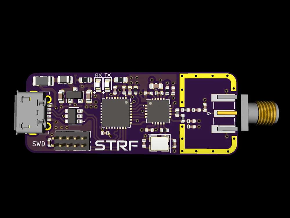
Research and analyze what is a radio frequency circuit

Research and analyze what is a radio frequency circuit

Radio frequency circuits are key components in wireless communication systems and are mainly responsible for transmitting and processing radio frequency signals.

Radio frequency signal is a high-frequency signal, whose frequency range usually ranges from tens of megahertz (MHz) to hundreds of gigahertz (GHz), or even higher.

The main function of the radio frequency circuit is to implement operations such as sending, receiving, amplifying, filtering, frequency conversion and modulation of radio frequency signals to support the normal operation of the wireless communication system.

radio frequency circuit

In wireless communication systems, radio frequency circuits usually consist of two parts: a radio frequency transmitting circuit and a radio frequency receiving circuit.

The radio frequency transmitting circuit is responsible for converting the information signal into a radio frequency signal suitable for transmission and radiating it through the antenna; while the radio frequency receiving circuit is responsible for receiving the radio frequency signal received by the antenna and restoring it to the original information signal.

In order to achieve these functions, RF circuits usually need to contain various RF components and components, such as filters, amplifiers, mixers, oscillators, modulators, etc. These components and components cooperate and work together to process and transmit radio frequency signals.

In specific applications, the design and optimization of radio frequency circuits is a complex process that requires consideration of multiple factors, such as signal frequency, power, bandwidth, noise, distortion, etc. At the same time, the size, weight, cost, reliability and stability requirements of the RF circuit also need to be considered.

In general, radio frequency circuits are an important part of wireless communication systems, and their performance directly affects the performance and reliability of the entire system. Therefore, the research and analysis of radio frequency circuits is of great significance and application value.

Research and analyze what is a radio frequency circuit

Basic concepts of radio frequency circuits

Radio frequency circuit is an electronic circuit that processes radio frequency signals, and its operating frequency range is usually from tens of megahertz (MHz) to hundreds of gigahertz (GHz), or even higher. Radio frequency signal is a high-frequency signal mainly used for wireless communication and transmission. In wireless communication systems, the main function of radio frequency circuits is to convert information signals into radio frequency signals suitable for transmission, and to send and receive them.

The composition of radio frequency circuit

Radio frequency circuits usually consist of two parts: a radio frequency transmitting circuit and a radio frequency receiving circuit.

RF transmitting circuit

Practical RF Hardware and PCB Design Tips – Phil’s Lab #19

The radio frequency transmitting circuit is responsible for converting the original information signal into a radio frequency signal suitable for transmission and radiating it through the antenna. The circuit usually contains components such as modulators, upconverters, power amplifiers, etc.

The modulator is used to modulate the information signal onto the carrier wave, the upconverter is used to convert the intermediate frequency signal into a radio frequency signal, and the power amplifier is used to amplify the power of the radio frequency signal for radiation through the antenna.

RF receiving circuit

Research and analyze what is a radio frequency circuit

The radio frequency receiving circuit is responsible for receiving the radio frequency signal received by the antenna and restoring it to the original information signal. This circuit typically contains components such as an antenna, low-noise amplifier, downconverter, demodulator, etc.

The antenna is used to receive radio frequency signals, the low noise amplifier is used to amplify weak radio frequency signals, the downconverter is used to convert the radio frequency signal into an intermediate frequency signal, and the demodulator is used to restore the intermediate frequency signal to the original information signal.

Characteristics and applications of radio frequency circuits

Features

  • High frequency: RF circuits process high-frequency signals, which have higher frequencies and shorter wavelengths.
  • Broadband: With the development of communication technology, the signal bandwidth processed by radio frequency circuits is getting wider and wider.
  • High gain: In order to achieve long-distance communication, high-energy signals need to be amplified and processed.
  • High sensitivity: In order to receive weak signals, a receiver with high sensitivity is required.
  • Integration: In order to reduce size and weight, many RF components are integrated on one chip.

Application

  • Wireless communication: Wireless communication systems such as mobile phones, wireless local area networks (WLAN), and Bluetooth are all inseparable from the support of radio frequency circuits.
  • Radar: Radar detects information such as the position and speed of targets by transmitting and receiving radio frequency signals.
  • Satellite communications: Transmission and communication between ground stations and satellites in satellite communications systems require radio frequency signals.
  • Radio navigation: Radio navigation systems determine information such as position and heading by transmitting and receiving radio frequency signals.

What is a radio frequency circuit used for

Radio frequency circuits are used in many fields, including wireless communications, radar, electronics, medical and life sciences, electronic games, aerospace, mobile communications, satellite communications, wireless broadcasting, radar, electronic radio frequency equipment, televisions, radio stations, microwave ovens, Medical imaging, drug research and development, biological detection, electronic game field, wireless microphone, wireless controller, near field communication, aerospace field, artificial satellite, space exploration, orbit control, satellite communication.

What are RF devices?

Radio frequency devices are the core of wireless connections and the basic components for signal transmission and reception, and have a wide range of applications. Specifically, RF devices include RF switches and LNAs, RF PAs, filters, antenna tuners and millimeter wave FEMs, etc. Among them, filters account for about 50% of the RF device market, RF PAs account for about 30%, RF switches and LNAs account for about 10%, and others account for about 10%. The difference between active RF devices and passive RF devices is that active RF devices use electrical power or electrical control signals to power the device and change its performance. In many cases, for amplifier and mixer biasing, active RF devices require direct power to function.

Advantages of RF circuits

The advantages of radio frequency circuits include fast transmission speed, strong anti-interference ability, wide application range, and high reliability.

What is the relationship between radio frequency circuits and circuits?

RF circuits are a special type of circuit used to process signals in the radio frequency band. The relationship between radio frequency circuits and ordinary circuits is that radio frequency circuits are a special form of circuits that process high-frequency signals, while ordinary circuits usually process low-frequency signals.

In radio frequency circuits, due to the high frequency of the signal, the size of the circuit and the length of the wire cannot be ignored relative to the wavelength of the signal. Therefore, the relevant theory of distributed parameters needs to be used to process the circuit. This means that in RF circuits, the propagation of a signal depends not only on the amplitude of the signal, but also on the phase and direction of the signal.

Compared with ordinary circuits, radio frequency circuits have some special properties and applications. For example, radio frequency circuits can be used in wireless communications, radar, satellite communications, measuring instruments and other fields, but the applications of ordinary circuits in these fields are limited. In addition, the design and production of RF circuits also require special technologies and tools, such as microstrip lines, strip lines, waveguides, etc.

In short, radio frequency circuit is a special form of circuit that processes high-frequency signals and has some special properties and applications. Although ordinary circuits are widely used in many fields, the application of radio frequency circuits is indispensable in fields that need to process high-frequency signals.

RF resistors, RF capacitors and RF inductors in radio frequency circuits

RF resistors, RF capacitors and RF inductors in radio frequency circuits

Radio frequency (RF) circuits are circuits that process signals in the radio frequency band. The radio frequency band covers the range from hundreds of kilohertz to hundreds of gigahertz and is widely used in wireless communications, radar, navigation and other fields.

In RF circuits, components such as resistors, capacitors, and inductors have special applications and characteristics.

RF resistor

In radio frequency circuits, the main function of resistors is to achieve signal attenuation and power consumption. Different from conventional DC resistors, RF resistors have some special properties under high frequency conditions.

First, RF resistors usually have very high resistance values because the energy of high-frequency signals is concentrated on the surface of the signal rather than in the center of the conductor. Therefore, the current path in the conductor is relatively small, resulting in increased resistance. In addition, due to the skin effect, current flows on the surface of the conductor, further increasing the resistance.

How to check RF transmitter and receiver || RF transmitter and rf receiver project

Secondly, the capacitive effect and inductive effect of radio frequency resistor cannot be ignored under high frequency conditions. This is because, as the frequency increases, the phase difference between current and voltage becomes significant, affecting the measurement of resistance value.

rf receiver circuit - rf receiver and transmitter

In order to provide stable resistance value in the radio frequency band, RF resistors are usually made of materials with low temperature coefficient and high stability, such as metal oxide ceramic materials. In addition, since the resistance of metal resistors changes with temperature, additional measures need to be taken to reduce this effect.

RF capacitor

RF Capacitor Resistor ByPass Circuit

In radio frequency circuits, the main function of capacitors is to filter and couple signals. Compared with conventional capacitors, radio frequency capacitors also have some special properties under high frequency conditions.

First, the capacitance of RF capacitors decreases as frequency increases. This is due to the fact that at high frequencies, the wavelength of the signal decreases, causing the coupling between the capacitor plates to decrease. In addition, the skin effect also reduces the flow of current between the capacitor plates, further reducing the capacitance value.

Secondly, the inductance and resistance effects of radio frequency capacitors cannot be ignored under high frequency conditions. This is because, as frequency increases, the inductance between the capacitor plates becomes the dominant effect, affecting the capacitor’s performance. Additionally, additional thermal noise and scattering effects occur due to the resistance of the capacitor plate.

rf inductor circuit

To reduce the impact of these effects, RF capacitors are often made of materials with low inductance and high Q value. Additionally, to reduce the effects of thermal noise, additional measures are required to keep the temperature of the capacitor plates stable.

RF inductor

In radio frequency circuits, the main role of inductors is to select and match signals. Compared with conventional inductors, radio frequency inductors also have some special properties under high frequency conditions.

First, the inductance of a radio frequency inductor decreases as the frequency increases. This is because under high-frequency conditions, the magnetic permeability decreases, resulting in a decrease in the change speed of the magnetic field. In addition, the skin effect also reduces the flow of current in the wire, further reducing the inductance value.

Summary of RF Resistors, RF Capacitors and RF Inductors

Secondly, the resistance and capacitance effects of radio frequency inductors cannot be ignored under high frequency conditions. This is because, as frequency increases, the resistance of the wire becomes the dominant effect, affecting the performance of the inductor. In addition, since changes in the magnetic field will generate an induced electric field, the RF inductor has a certain capacitive effect.

To reduce the impact of these effects, RF inductors are often made of materials with high magnetic permeability and low resistance. In addition, in order to reduce the influence of the induced electric field, additional measures need to be taken to reduce the coupling between the inductor coils.

Summary of RF Resistors, RF Capacitors and RF Inductors

To sum up, RF resistors, RF capacitors and RF inductors all play an important role in radio frequency circuits. Due to their special applications and characteristics, these components require special materials and manufacturing processes to ensure their performance.

With the continuous development of wireless communication technology, the performance requirements for radio frequency components are becoming higher and higher. Therefore, research and development of new high-performance radio frequency components is one of the current important research directions.

RF resistors, RF capacitors and RF inductors in radio frequency circuits

E-components.globalbestshopping.com is a Chinese electronic component manufacturer and distributor, providing global electronic component brands. Globalbestshopping electronic component manufacturer is committed to providing high-quality, reliable and durable electronic components to meet the needs of the growing electronics market.
We have advanced production equipment and a complete quality management system to strictly control product quality.
At the same time, we continue to innovate, develop more competitive products, and provide customers with one-stop solutions. As a leader in the industry, we always adhere to the business philosophy of customer first and quality first, and work hand in hand with customers around the world to create a better future.

Radio frequency RF circuit design and layout

Radio frequency RF circuit design and layout

Radio frequency RF circuit design and layout are key links in wireless communication systems. Factors such as impedance matching, electromagnetic compatibility, power control and stability need to be comprehensively considered to ensure signal transmission quality.

Radio frequency RF circuit design and layout

The layout must follow the principles of modularity, electromagnetic shielding, power supply and grounding, wiring and heat dissipation design to improve circuit performance and stability. Verify the feasibility and effectiveness of the design through simulation and testing, providing strong support for the development of wireless communication technology.

Radio Frequency RF Circuit Design and Layout Overview

Radio frequency RF circuit design and layout YouTube tutorial

Radio frequency (RF) circuit design is a key link in wireless communication systems, involving many aspects such as the propagation of electromagnetic waves, circuit response characteristics, and material properties.

Layout is an important part of RF circuit design, which affects the performance, stability, reliability and cost of the circuit. When designing and laying out RF circuits, various factors must be fully considered to ensure the feasibility and effectiveness of the design.

Radio frequency RF circuit design principles

  1. Impedance matching: In radio frequency circuits, signal transmission is affected by impedance. In order to ensure smooth transmission of signals, impedance matching between the source and load must be achieved. Through reasonable design, making the output impedance of the source equal to the input impedance of the load can effectively reduce signal reflection and loss.
  2. Electromagnetic compatibility: In radio frequency circuits, the frequency of signals is relatively high, which is prone to electromagnetic interference. Therefore, electromagnetic compatibility issues should be fully considered in the design and effective measures should be taken to reduce interference between different modules.
  3. Power control: In wireless communications, power consumption is an important consideration. The transmit power should be reasonably controlled to ensure signal coverage and transmission quality, while avoiding interference with other frequency bands.
  4. Stability considerations: The working environment of radio frequency RF circuits may be complex, and its stability should be fully considered. During design, stable materials and processes should be used to reduce the impact of environmental factors such as temperature, humidity, and pressure on circuit performance.

Radio frequency RF circuit layout principles

  1. Modular design: Divide the radio frequency RF circuit into different modules, each module is responsible for a specific function. The modular design facilitates maintenance and upgrades and can improve the reliability and stability of the circuit.
  2. Electromagnetic shielding: During layout, electromagnetic shielding of key components should be considered to reduce the impact of electromagnetic interference on circuit performance. Protecting sensitive components through metal shells, conductive materials, etc. can effectively suppress interference from external electromagnetic waves.
  3. Power supply and grounding: Reasonable power supply and grounding design are the basis for ensuring the normal operation of radio frequency RF circuits. The stability and reliability of the power supply should be ensured to avoid the impact of power supply fluctuations on circuit performance. At the same time, good grounding can effectively reduce electromagnetic interference and signal leakage.
  4. Wiring: Wiring is an important link in layout and directly affects the performance of the circuit. The principle of “short, straight and wide” should be followed to reduce loss and reflection during signal transmission. For key signal lines, multi-layer wiring and wire diameter optimization can be used to improve their performance.
  5. Heat dissipation design: Since radio frequency RF circuits generate a large amount of heat when working, heat dissipation design is crucial. Factors such as heat dissipation paths, heat dissipation materials, and heat dissipation methods should be fully considered to ensure that the temperature of the circuit is stable during operation and to avoid performance degradation or damage due to overheating.

Physical and electrical partitions

In radio frequency RF circuit layout, physical partitioning and electrical partitioning are two important concepts. Physical partitioning mainly involves issues such as the layout, orientation, and shielding of components; electrical partitioning can continue to be decomposed into partitions for power distribution, RF wiring, sensitive circuits and signals, and grounding. Through reasonable physical and electrical partitioning, the performance and stability of the circuit can be improved.

PCB stack design

PCB stack-up design is one of the important factors affecting the performance of radio frequency RF circuits. In the design, the main ground plane (main ground) should be arranged on the second layer under the surface layer, and the RF lines should be arranged on the surface layer as much as possible. This can reduce loss and interference during signal transmission and improve signal quality. In addition, reasonable PCB stacking design can also reduce the thickness and weight of the circuit, which is conducive to achieving thinning and miniaturization requirements.

Simulation and testing

After completing the radio frequency RF circuit design and layout, simulation and testing need to be performed to verify its performance. By using professional simulation software to perform electromagnetic simulation and optimization of the circuit, its performance under different conditions can be predicted. At the same time, actual testing is also a necessary link. Test data can verify the feasibility and effectiveness of the design, and improve and optimize existing problems.

Summary of radio frequency RF circuit design and layout

To sum up, the design and layout of radio frequency RF circuits is a complex and delicate process. In actual work, it is necessary to comprehensively consider multiple factors and conduct comprehensive evaluation and optimization from aspects such as impedance matching, electromagnetic compatibility, power control, and stability. Through continuous improvement and improvement of design and layout solutions, the performance, stability and reliability of radio frequency RF circuits can be improved, providing strong support for the development and application of wireless communication technology.

What factors need to be paid attention to in radio frequency RF circuit design?

https://www.youtube.com/watch?v=_vojnN0WeuU&list=PLqJXLMMCqzEfuT5hG611224h3EslEQdK4&index=4
How To Use A RF Transmitter And Receiver?

In radio frequency RF circuit design, there are several key factors that require special attention:

Signal integrity and power integrity

Signal integrity and power integrity are important factors to consider in radio frequency RF circuit design. Signal integrity mainly focuses on the quality of the signal during transmission, including the amplitude, frequency, phase and other characteristics of the signal. Power integrity focuses on power distribution and decoupling issues, including voltage drop, power supply noise, and decoupling capacitor selection.

electromagnetic compatibility

Due to the high operating frequency of radio frequency RF circuits, the problem of electromagnetic interference is more prominent. In the design, a series of measures, such as electromagnetic shielding, filtering, grounding, etc., need to be taken to reduce electromagnetic interference and ensure the stability and reliability of the circuit.

Place and route

Layout and wiring are a very critical part of RF circuit design. Reasonable layout can improve the performance and stability of the circuit while reducing the size and cost of the circuit. When wiring, you need to pay attention to parameters such as the length, width, and spacing of signal lines to reduce loss and interference during signal transmission.

Thermal design

Since RF circuits generate a large amount of heat when operating, thermal design is also a factor that needs to be considered. When designing, factors such as heat dissipation paths, heat dissipation materials, and heat dissipation methods need to be fully considered to ensure that the temperature of the circuit is stable during operation and to avoid performance degradation or damage due to overheating.

Reliability design

Radio frequency RF circuits are usually used in wireless communications, radar, navigation and other fields, and have high requirements for reliability. When designing, it is necessary to consider factors such as the life of components and the impact of the working environment, and take corresponding measures to improve the reliability of the circuit.

In the design of radio frequency RF circuits, the above factors need to be considered comprehensively, and simulation and testing must be performed to verify their performance. Through continuous improvement and design improvement, the performance, stability and reliability of radio frequency RF circuits can be improved, providing strong support for the development and application of wireless communication technology.

How to verify the performance of radio frequency RF circuits?

Verifying the performance of an RF circuit is an important step to ensure that the circuit’s performance meets design requirements. Here are some common verification methods:

  1. Spectrum analysis: Use a spectrum analyzer to measure the frequency response of a circuit to check for the presence of unwanted frequency components or spurious signals.
  2. Power test: By measuring the output power of the circuit, verify whether it meets the design requirements. Measurements can be made using devices such as power meters.
  3. Noise test: Evaluate the noise performance of the circuit, including noise coefficient, signal-to-noise ratio and other parameters. This can be measured using equipment such as a noise analyzer.
  4. Distortion test: Check the distortion performance of the circuit, such as harmonic distortion, intermodulation distortion, etc. Measurements can be made using equipment such as a distortion analyzer.
  5. Sensitivity test: Test the receiving sensitivity of the circuit and check the performance of the circuit under low signal strength. Measurements can be made using equipment such as signal generators and spectrum analyzers.
  6. Phase noise test: Evaluate the phase noise performance of the circuit and check the performance of the circuit at high frequency offset. Measurements can be made using equipment such as a phase noise analyzer.
  7. Intermodulation test: Check the intermodulation performance of the circuit under different frequency signals. Measurements can be made using equipment such as signal generators and spectrum analyzers.
  8. Transmission characteristic test: Test the transmission characteristics of the circuit, such as insertion loss, return loss and other parameters. Measurements can be made using equipment such as network analyzers.
  9. Stability and reliability testing: Test the stability and reliability of the circuit through long-term operation and accelerated life testing.
  10. Electromagnetic compatibility test: Verify the electromagnetic compatibility of the circuit and check whether it meets the requirements of relevant standards and specifications. You can entrust a professional electromagnetic compatibility testing agency to conduct testing.

In summary, the above methods can help verify the performance of radio frequency RF circuits. In actual testing, appropriate methods can be selected for measurement and analysis based on specific circumstances to ensure that the performance of the circuit meets the design requirements.

How to ensure electromagnetic compatibility in radio frequency RF circuit design?

In radio frequency RF circuit design, electromagnetic compatibility is an important issue. To ensure electromagnetic compatibility, the following measures can be taken:

  1. Reasonable partitioning: Divide the circuit into different areas according to function, and ensure that high-power RF and low-noise parts are isolated. This reduces the possibility of mutual interference and signal leakage.
  2. Electromagnetic shielding: Use metal shells or conductive materials to shield key parts to reduce interference from external electromagnetic waves. At the same time, it can also prevent sensitive signals from leaking to the outside.
  3. Filter design: Add filters at the power input and signal line entrances to reduce the possibility of external interference signals entering the circuit.
  4. Good grounding: Ensure good and stable grounding, which can effectively reduce electromagnetic interference and signal leakage.
  5. Wiring strategy: Use short, straight, and wide wiring principles to reduce loss and reflection during signal transmission. For key signal lines, multi-layer boards and optimized wire diameters can be used for wiring.
  6. Component selection and layout: Select components with low noise and low power consumption, and arrange them reasonably to reduce mutual interference between components.
  7. Software simulation and testing: Use electromagnetic simulation software to predict and optimize before design, and verify the feasibility and effectiveness of the design in actual testing.
  8. Comply with standards and specifications: Follow relevant electromagnetic compatibility standards and specifications during the design process to ensure that the design meets industry requirements.

In summary, through measures such as reasonable zoning, electromagnetic shielding, filter design, good grounding, wiring strategies, component selection and layout, software simulation and testing, and compliance with standards and specifications, the electromagnetic compatibility of radio frequency RF circuits can be effectively improved. Ensure its performance is stable and reliable.

What are the principles of radio frequency RF circuit design?

In radio frequency RF circuit design, the following principles need to be followed:

  1. Isolate the high-power RF amplifier (HPA) and the low-noise amplifier (LNA) as much as possible. Simply put, keep the high-power RF transmit circuit away from the low-power RF receive circuit. This can avoid mutual interference and signal leakage, and improve the performance and stability of the circuit.
  2. Make sure that the high-power area on the PCB board has at least a whole piece of ground, preferably without via holes. Of course, the larger the copper foil area, the better. This can reduce loss and interference during signal transmission and improve heat dissipation.
  3. Circuit and power supply decoupling is also extremely important. Through reasonable decoupling design, the impact of power supply fluctuations on circuit performance can be reduced and signal integrity improved.
  4. The RF output usually needs to be located far away from the RF input. This can avoid signal reflection and mutual interference, and improve the performance and stability of the circuit.
  5. Sensitive analog signals should be kept as far away from high-speed digital signals and RF signals as possible. This can reduce the interference of digital signals and RF signals on analog signals and improve the performance and stability of the circuit.
  6. Follow the modular design principle and divide the radio frequency RF circuit into different modules, each module is responsible for a specific function. This can improve the reliability and stability of the circuit and facilitate maintenance and upgrades.
  7. Consider electromagnetic compatibility and take effective measures to reduce interference between different modules. The impact of electromagnetic interference on circuit performance can be reduced through electromagnetic shielding, filtering, grounding, etc.
  8. Consider the power supply and grounding design to ensure the stability and reliability of the power supply and avoid the impact of power supply fluctuations on circuit performance. At the same time, good grounding can effectively reduce electromagnetic interference and signal leakage.
  9. Follow wiring principles, such as “short, straight, wide”, etc., to reduce loss and reflection during signal transmission. For key signal lines, multi-layer wiring and wire diameter optimization can be used to improve their performance.
  10. Consider thermal design. Since RF circuits generate a large amount of heat when working, factors such as heat dissipation paths, heat dissipation materials, and heat dissipation methods need to be fully considered to ensure that the temperature of the circuit is stable during operation and to avoid performance degradation or overheating. damage.

To sum up, the above principles are the basic requirements that need to be followed in the design of radio frequency RF circuits. By comprehensively considering these factors and continuously optimizing the design, the performance, stability and reliability of radio frequency RF circuits can be improved, providing strong support for the development and application of wireless communication technology.